Thursday, March 16, 2017

"The Sliding Challenger" - by Pat Pending

The following was offered by my friend Pat Pending as an exercise to build an amplifier with minimum parts using the EMOS. 3 watts from one active device could be a crystal radio builders delight. Kiss the LM386 goodbye? Now Pat's circuit:


I've always been interested in vintage electronics, and the methods that the engineers and technicians used to overcome design problems in bygone days.

One such example is from the early transistor era. Transistors then were very expensive, and the desire to make savings with production costs were sought, class B push pull amplifiers with their two output transistors were costly to produce, and the class A alternative suffered from high power consumption, not only that, they also consumed the same power regardless of the required audio output, because the quiescent current in the output device had to be set so as to handle the maximum without distortion. The fixed bias class A output stage has a maximum theoretical efficiency of 50% falling to 0% at minimum output.

Enter the sliding bias amplifier. The principle is to provide "just enough" drive to the output device to allow it to handle the incoming signal level without distortion, in simple arrangements there are two main methods that were used, feedback biasing, where a part of the amplifier output is rectified and used to provide output drive, and feed forwards biasing, where part of the drive signal is used to provide DC bias, the later method is the one that has the potential to create less distortion in the output as the increase in drive bias is available the instant the signal increases, well, in theory at least.

Sir Douglas Hall K.C.M.G., M.A.(Oxon), devised such a circuit that was published in the "Radio Constructor" magazine in August 1970 entitled "The Sliding Challenger", the circuit contained three bipolar transistors, and had a power of 250mW. His intention was that it would be used by the hobbyist as an output stage in home brew battery powered radios as an alternative to the common class B topology

One of the problems that the circuit suffers is that as the output device drive is provided by the applied signal, and therefore requires an extra stage of amplification, to provide enough drive. After a discussion about eMOS-FET transistors I decided to see if the high input impedance of the mos transistors could be the answer, allowing the construction of an effective one transistor audio stage.

The circuit suggested provides the adjustable voltage bias to the gate of the device to VTh making it operate in saturation mode, the bias is applied through a diode to produce a clamp that sits the drive signal atop the fixed voltage, theoretically the device never running out of drive. If the circuit is built and the drive is insufficient, try different values for the capacitor/series resistor that are between drain and gate.The only setting up proceedure is to measure the drain current and adjust the bias so that e-MOS passes 10-15 mA at no signal,

the zener diode voltage is chosen to be just above VTh for the e-MOS used, the transformer version had a 10:1 impedance ratio (3.16:1 turns ratio). If its preferred to direct couple the speaker, a higher resistance coil is needed as per the second diagram, and at higher powers it must be remembered that there will be a DC displacement of the speaker cone, so the handling capacity must be halved to prevent damage. The transistor used in the example was a T03 IRF450 that was to hand, (a very expensive and high power device!) and in the transformer version produced 3W approximately at 10% THD with an input signal of 2.5VRMS,and supply of 12volts.

No one would dare suggest that this technology should be revived for use in the modern age but it is an interesting experiment none the less.


Monday, March 13, 2017

Lambda diode oscillator using discrete JFETs

lambda diode

edit 3: The circuit consist of the lambda diode, a coil, and a 3 volt supply. It is driving a diode ring mixer.

edit 2: The current peaks and then drops off when the supply voltage is increased. The 200 ohm resistor is not needed. the waveform appears smoother without the limiter resistor.

edit 1: I was playing with the lambda using J112 and J176 JFETs. With them connected face to face. The JFETs Mr Vargas uses have a different pin out. It worked for me so I had to look closer. The JFETs I'm using are symmetrical so the drain and source are interchangeable. My odd ball circuit was working the same because the device would allow me to connect it backwards and still work. 
After discovering this I did another with the pins matched as shown and it did seem just a tad better.

I was looking at the Lambda diode and found this article which is about building IET ( Instantaneous Electronic Trips) Using a J112 and a J176 to build the portion of the circuit labeled T1 and T2 produces a diode that will peak at around 5 - 6 ma and drop to zero at 12 - 15 volts. The perfect Lambda for a quick and easy oscillator. I put a 200 Ohm resistor from T1 drain to +Vcc and a tank from the source of T2 to -Vcc. She sings! I put the prototype in a project box with a RCA jack for the coil. It oscillates with the coils from my GDO from a few 100 Khz to beyond 10 Mhz.

Clipping that with my Double Balanced Mixer and hearing aid amp makes a good performing radio. It was oscillating with a 3 Volts supply. I'll have to put the pieces together in one chassis.

I think a regulated power supply and slug tuning will produce a winner.

Wednesday, January 11, 2017

Putting the 80 meter receiver in one place.


 This is the circuit Tom posted. I modified the tuning and regeneration controls. This one works if you have the components. The modification allows for components parameters variations and works with different JFETs. I made a couple of AF output stages for it.

The coil is detailed here:

tuning coil detail

This is the circuit introduced by tom with my modifications.

 I gave the audio output a little boost with this pre amp.

This is the audio amp I am using.

The Audio Amp

 2 watt amp. Connected the 5.6K resistor to the tap between the 3.3Ohm resistors.

Tuesday, December 27, 2016

Alternate RF gain for the Odd To Me Regen

There is always someone finding a problem with whatever is posted. The original circuit used an established method. It has been in use for about 20 years. Here is a little more complicated circuit that may work better. The only problem I had with the original is the RF gain is the volume control so when you turn it up on a weak signal and then get a boomer on channel it may tend to hurt your ears. The diodes used here limit the peaks and help prevent the ear damage. It can be switched from balanced to unbalanced by installing or removing the jumper. This particular circuit has been used in commercial units since the '60s.

Saturday, December 24, 2016

The Odd-to-me SW regen update.

The original circuit and the fix. 
I'm not a big fan of the LM386. This is my AF stage. NOTE: Use a 100K pot with the receiver to prevent overloading the detector.
Here is the circuit I built. I'm using slug tuning and diode tuning. I'm using a 9 volt supply. The posted version used a 5 volt circuit.

Here is the modified circuit with the AF amp.

Friday, December 23, 2016

Exploring the world of 3DQ or the mystery of zero bias devices

If you say zero bias in the wrong places they will start collecting fire wood and a stake. Let's don't go into this with a closed mind. After all the manufacturer named these devices. Even if the device is not zero bias the term is being used to define a new class of device. Now that I've set the ground rules here we go.
Hold on it will be a quick run threw without a lot of discussion. I will try to let the datasheets tell the story.
UHF ,high gain, low noise, and dual gate. It's a cascode amplifier. Look at the drain current? Plus or minus 30ma? What's up with that? Can the drain conduct in either directions? That's what it says. Let's turn the page and see what else we see.

Look at the center graph at the top of the page. It conducts at zero volts bias and can respond to positive or negative gate voltage. Ummm! It's and enhancement depletion device! As I said above it's a new family of devices. Let's look at a 'normal' MOSFET for a moment and compare.

We don't have to look at much more than the symbol. The 2N7002 has a protection diode built in to keep the drain current from reversing. If you use a MOSFET in an inductive load it needs a protection diode to keep the inductive kick back from destroying the device.

The depletion MOSFET conducts with no bias and can be biased into higher or lower conduction. This is accomplished by doing an extra step is the doping that enhances the channel. While this is not new and exciting technology it seems when it was new it failed to be exciting enough to become common place to us hobbyist. Now for the good news. These devices are still being made. A quick check on Ebay for 3DQ finds some at $5.50 each. Seems they are obsolete.  But a the depletion MOSFET is alive and well.

This circuit is built using a DN3545 MOSFET. The schematic is for a 'normal' enhancement MOSFET. It would require biasing to conduct. I made the circuit with a Depletion N channel 3545. I did use a 1 meg gate resistor but no forward bias resistor. My plan is to build a ham receiver 80 and 40 meter. I'm sending it a 4 Mhz signal in the test. So it requires no bias and works at 4 Mhz. I think the term zero bias would apply. Now that we know what to look for we can find 3DQ equivalents a lot cheaper. I think I paid 10 cents each for the last ones I bought.
Just look for Depletion in the name.

Friday, December 16, 2016

Making a slug tuned coil with pictures.

My explanation without pictures was a bit confusing. I had a little shop time today and made a new coil. I took the camera along to document the process.
I used this plastic stock for my pads. You can use any insulator. I have used wood but I used an insert in the wood so I could have threads that wouldn't wear out to quickly.

I didn't do any measuring I just cut a piece and used it to size the next piece.
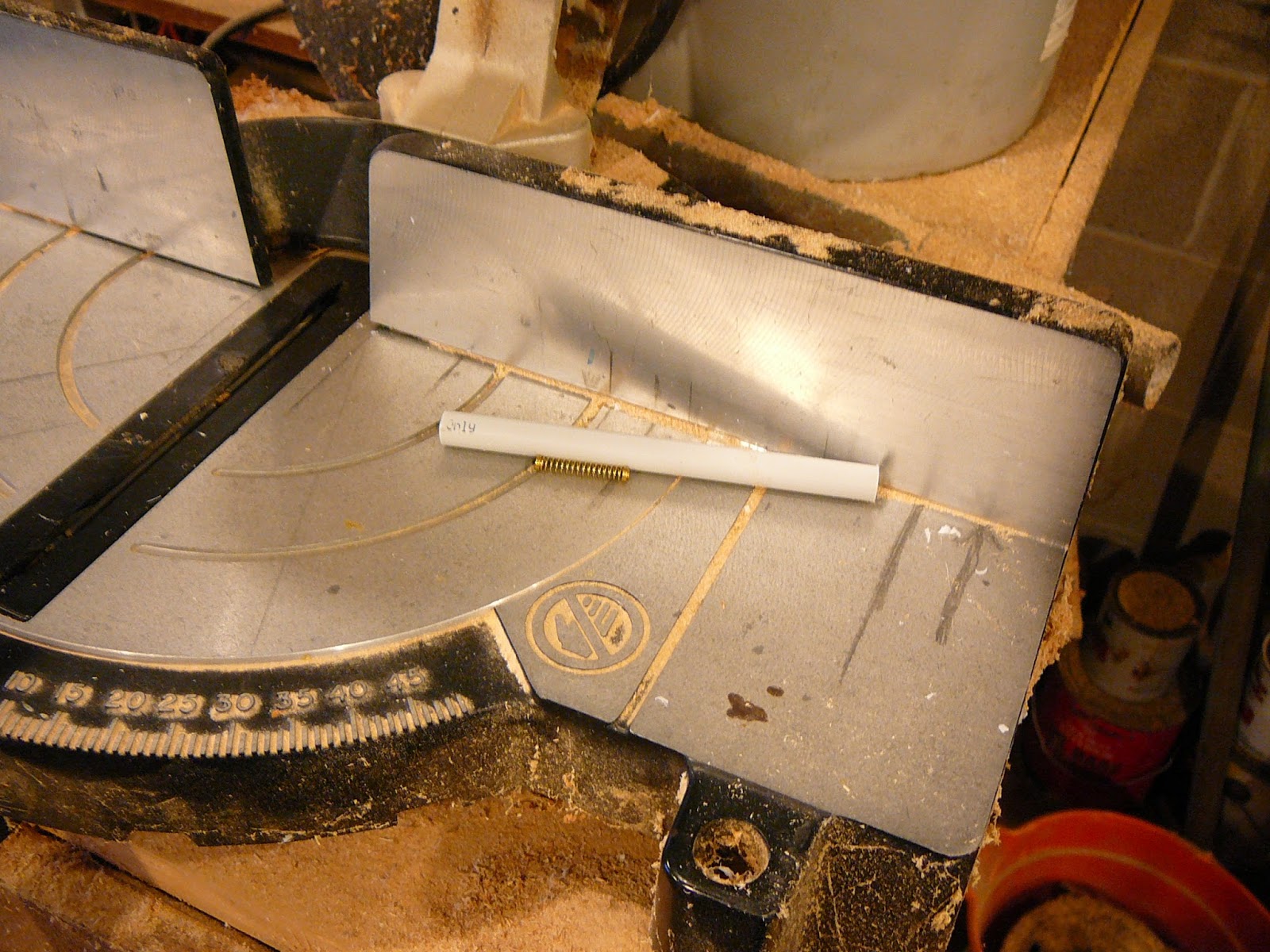
The tube is a sink supply. You can use a plastic pipe. I like the sink drain because the slug fits snugly in it.
I just cut off a piece for the core. I made it a little long and had to trim it. About a hands width is good.
I clamped the two block so they will stay lined up as I drill them.
I just drilled a 1/8" hole about 5/8" from the top. The block being clamped in line will cause the holes to line up in final assembly.
I want to make a snug fitting hole for the former so I select a bit to fit.
I set the drill press to drill half way through.
Another view to show the bit stop is set half way.
The holes are drilled and the fit tested. It is snug.
This is what it will look like when assembled. The reason for drilling both pieces together was to keep the former level.
My rod is a 1/4" brass screw. I need one end threaded to match it.
If you don't have a sink supply and don't want to buy one you could use whatever is on hand. Here I show the core will fit a Bic pin barrel.
I threaded the end cap and have started the core into it.
You could but a brass screw that is threaded. I'm using a screw left over from a plumbing job and had to thread it.
The final assembly except for a knob.
I save whatever I think I might use later. This is a knob from the junk box. The opening is flat on two sides. No problem a few strokes with a file and it fits snugly.
The knob on the shaft.
This is what the finished product looks like. The only thing left is how to mount it.
I drilled a small hole in the bottom of each block for mounting screws. While I was at it I drilled a hole in the top of each block. I decided to terminate the wires on the blocks.
I installed the pins for the wire termination.
I put a couple of self tapping screws in the bottoms.
The final product ready to wind coil and mount.
I looked in the bench drawer and found a roll of wire to wind the coil with. Wound the coil and soldered it to the terminal pins.
I'm ready to mount the coil. You could measure and mark but I just laid the coil on its side and marked the holes in line with the screws.
I have drilled the holes and placed the board over the coil to check the alignment.
I screwed the screws into the block threw the board.
The coil mounted on the board and ready for a build.
Just another view. The meter reads 16uh to 23uh.
This is my audio amp.
This is the radio complete with pilot light. There is a LED in the hole under the switch.
The back side of the board. It isn't pretty but it work

Another version of variable inductor