My explanation without pictures was a bit confusing. I had a little shop time today and made a new coil. I took the camera along to document the process.
 |
| I used this plastic stock for my pads. You can use any insulator. I have used wood but I used an insert in the wood so I could have threads that wouldn't wear out to quickly. |
|
|
 |
| I didn't do any measuring I just cut a piece and used it to size the next piece. |
 |
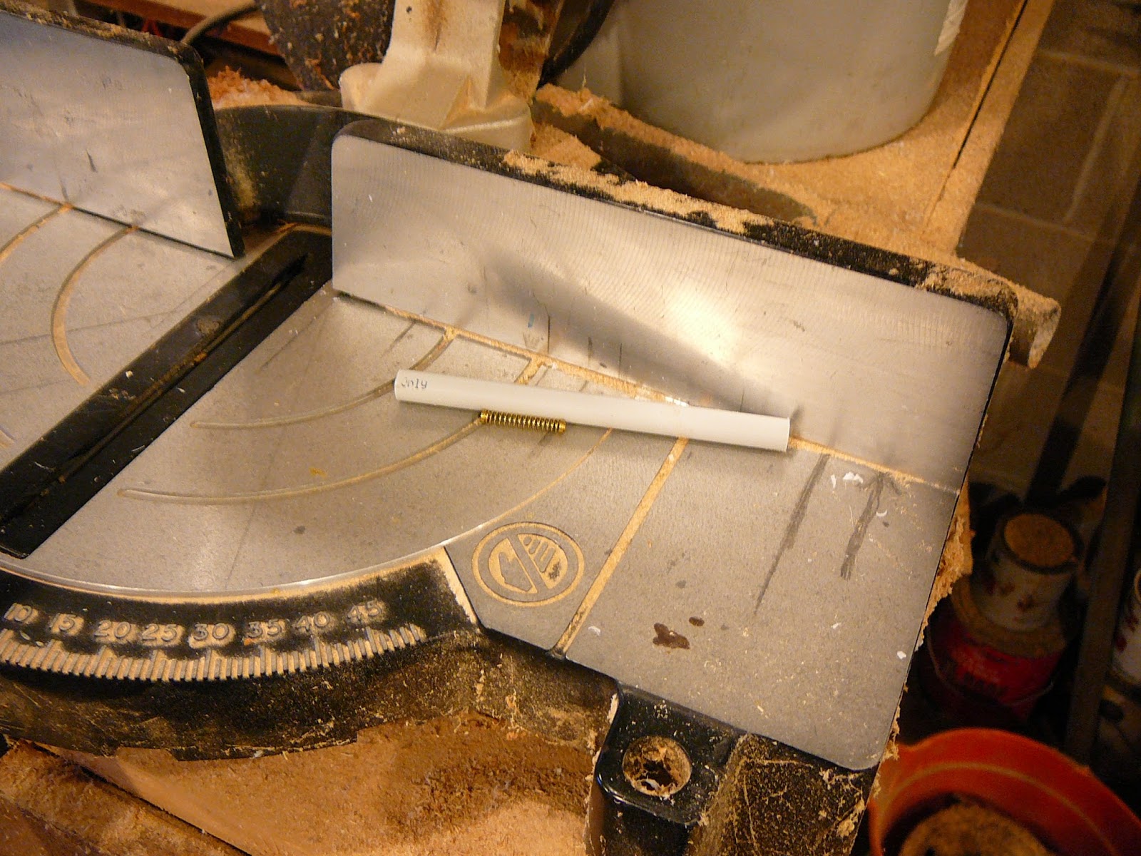
| The tube is a sink supply. You can use a plastic pipe. I like the sink drain because the slug fits snugly in it. |
I just cut off a piece for the core. I made it a little long and had to trim it. About a hands width is good.
I clamped the two block so they will stay lined up as I drill them.
I just drilled a 1/8" hole about 5/8" from the top. The block being clamped in line will cause the holes to line up in final assembly.
I want to make a snug fitting hole for the former so I select a bit to fit.
I set the drill press to drill half way through.
Another view to show the bit stop is set half way.
The holes are drilled and the fit tested. It is snug.
This is what it will look like when assembled. The reason for drilling both pieces together was to keep the former level.
My rod is a 1/4" brass screw. I need one end threaded to match it.
If you don't have a sink supply and don't want to buy one you could use whatever is on hand. Here I show the core will fit a Bic pin barrel.
I threaded the end cap and have started the core into it.
You could but a brass screw that is threaded. I'm using a screw left over from a plumbing job and had to thread it.
The final assembly except for a knob.
I save whatever I think I might use later. This is a knob from the junk box. The opening is flat on two sides. No problem a few strokes with a file and it fits snugly.
The knob on the shaft.
This is what the finished product looks like. The only thing left is how to mount it.
I drilled a small hole in the bottom of each block for mounting screws. While I was at it I drilled a hole in the top of each block. I decided to terminate the wires on the blocks.
I installed the pins for the wire termination.
I put a couple of self tapping screws in the bottoms.
The final product ready to wind coil and mount.
I looked in the bench drawer and found a roll of wire to wind the coil with. Wound the coil and soldered it to the terminal pins.
I'm ready to mount the coil. You could measure and mark but I just laid the coil on its side and marked the holes in line with the screws.
I have drilled the holes and placed the board over the coil to check the alignment.
I screwed the screws into the block threw the board.
The coil mounted on the board and ready for a build.
Just another view. The meter reads 16uh to 23uh.
This is my audio amp.
This is the radio complete with pilot light. There is a LED in the hole under the switch.
The back side of the board. It isn't pretty but it work
Another version of variable inductor


No comments:
Post a Comment