Sunday, August 26, 2018

Making the tie points for the coil

As you can see the loops are on the fiber glass rod. You could simply solder the lead wires to the wires and leave the rod but the single turn loops would be hard to keep from shorting out.
I simple took my needle nose pliers and put a little twist in each loop. I staggered the single turn taps to make it easier to connect to them without shorting them out.
If you want to avoid the soldering you can make the loops about 5 or 6 inches long and twist them at each point as you wind the coil. This will work but you will have a lot of tags to keep up with while winding the coil.

winding a 20 tap coil

The switch on the left is the units selector and the one on the right is the tens. They are able to select from 10 to 109 turns a single turn at a time.As you can see I have an armature on the left hand switch. when I cut the bar I will make another for the right hand switch.
I put a little glue around the contacts on the bottom to help harden the board and seal moisture out. The screw has a terminal lug and spring to maintain contact while allowing the switch to turn without the wire twisting with it.
When it is wired I will have 10 turns with both switches in the center position. Moving the units switch CCW will increase the turns to 19. Moving the tens switch one click CW will give 29. Rotating the units switch CW will produce 20 turns. And so it goes. We can have 10 turns to 109 turns.
I used a paper towel core and a 1/4" fiber glass rod to wind the coil. You could use a pen or pencil with a straight shank. I simple wound 10 turns around the core and rod then nine on the core one on the core and rod etc. I pushed the wire under the rod with my thumb and put some Q-dope on the coil. After the dope cures I'll remove the rod and twist the loops to make a place for my connections.

Note: If you have no Q-dope use clear finger nail overcoat or varnish.


Wednesday, August 22, 2018

Monday, August 20, 2018

avalanche and tunnel effect in semi conductors

Mr Polyakov explains this in his book "Semi Conductors made simple". If you read the book it may help with semiconductor theory. If you know the basics and just have the specific question page 95 is a good place to look for your answer. The book is here:

Polyakov - Semiconductors made simple


Saturday, August 18, 2018

making Q-Dope


If you have deep pockets you can just buy some for about $5 an ounce accept the health risk and skip the rest of the post. Otherwise you can make it for about $3 a half pint.This is what you need.
 100% acetone nail polish remover 1$.
 Ping pong balls about a quarter each.
Cut up the balls and put them in a glass container. Add acetone to the glass container. (do not use a plastic container unless you know it is acetone resistant.) The bottle the acetone came in will work after you use some and make room for the balls. Let it sit over night and you have this white glue. I use one ball per ounce of acetone and have good results.
Basically this is liquid celluloid. You can use it to make coil forms and as Q-Dope.
I wrapped a paper towel around a paper tube and coated it with the dope. After two or three coats I have the form for my next coil.
I have used the Q-Dope and it is good stuff BUT it is MEK based. Many years ago MEK was banded from my work place as a health hazard. The home brew using acetone is a safer compound. ( I don't see the warnings on the label for the polish remover.) The balls are 75% cello and 25% camphor. It seems the camphor is the most hazardous part of the mix. I rub Mentholatum on my skin to ease sore muscles and stuffy head. It is 9% camphor?
Anyway you can dissolve the balls and paint the solution on a coil. Let it dry and your coil is plastic coated. Make a paper core and paint it with the mix and when it drys you have a coil form. ( this may take a few coats.)
It's about the journey. Enjoy the trip.


Friday, August 17, 2018

loop update

A quick update on this project. When I installed the plastic tubing for the wire hangers I let it protrude out front and back.
When I blow it up it became a little grainy but you can see the tube. I wrapped one side with a single turn and the other with the ribbon cable. When I get back to the loop I will put a switch so I can select the taps on it. One side will be antenna and ground the other side will be the radio input.
The switch taps will be the terminals for the coil. I may come back and put ribbon on the side with the single loop after I see how it works.

I checked the single turn and it was about 12 uh. If memory serves I didn't write it down.

selector switch knob selection

As I said there are several options. I'm still looking a a couple. I didn't get any shop time today but I did bring in the knob I started yesterday.
I filled the cap with Durham wood putty.
I did two while I was mixing putty.
I plugged one into the board I made yesterday. I may want to paint it? It does look like a good size for my board.
I mounted an armature on it. I think that will be a go. Next shop time I can paint a couple caps and cut some banding for the armatures.
The grooves on the bottle cap make a good grip. I will need to lock the armature with a set screw or some glue. The Durham putty can be drilled and tapped. A little construction cement would work it a fellow didn't want to drill and tap a hole.


Thursday, August 16, 2018

winding a coil with taps and planning the build

I needed a core so I saved a paper towel core from the trash bin. I "varnished" it with some nitrocellulose based nail polish overcoat. Then gave it 3 or 4 spiral wraps with scotch tape.
I wound the coil with #32 magnetic wire with 20 turns between taps. My tester gives the following readings.
33uh
106uh
205uh
327uh
426uh
560uh
705uh
873uh
1022uh
I did a new board Mr Dave style today.
I used strapping material (banding material) for the armatures. The left is two pieces and the right one is a single strip. They both work but the left one is 'smoother'. I'll have to redo the right one.
The plan I'm forming is to use the left one with a coil like the one I wound last night and the right one selects a band by selecting a fixed capacitor.
1000pfd
900pfd
800pfd
700pfd
500pfd
400pfd
200pfd
100pfd
50pfd
10pfd
Then use a small variable cap for the band spread.
Again a tip of the hat to Mr Dave for suggesting the fixture screws.


Wednesday, August 15, 2018

Building a coil tap selection switch

I have to many projects on the bench and need to try a complete unit. I have the RF amp, detector and AF amp looking good so what I need is a tuner. I'm using the 1920's crystal set as my basic circuit. What I'm looking at is like this.
The selector picks the tap on a coil and the dial adjust the tuning capacitor. Simple enough by probably more ways to do it than there are people reading this blog ;). The thing to look at today is the switch. a simple stud switch with stops to prevent the user turning it to far in either direction.
Here is another with screw stops.
Elmer's work around was to put terminals on the end tap front side.
This guy simply lets the switch rotate without any stops. This could be adjusted to more or fewer taps so something to keep in mind. What about the studs? The studs are post were more like like rivets but could have been screws.

The semi tubular rivet was used when the wires were soldered to the back.  Not readily available today? Pricey.
You could use eyelets. The ones used on shoes might be a good size. The only problem here is the hole in the middle. It could be filled with solder, maybe?
I used screws on this one and it works fairly well. I'm still working on the armature (slider). I've tried a couple of different types and have not settled on one yet.
I like this one better than the one above. It is smoother and less click as it is moved.

Pop rivets will work too. The hole in the center and a method of attaching the wires is the draw back with them.


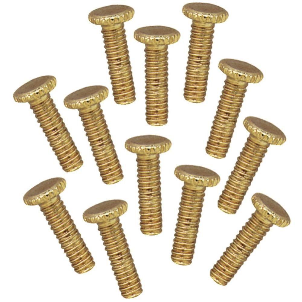
The founder of The Radio Board (Mr Dave) used these with good results. Fixture screws hold the globe on ceiling fan light fixtures.

I plan to use fixture screws but for the proof of concept will use screws. I have the prototype assembled except the armature.It will need a knob. I have the glue drying on the knob and will finish it tomorrow.
The knob to be. I put a drop of glue in the center of the lid. Tomorrow I'll fill the lid with some putty (or plaster of Paris) . After I thread the armature on the screw it will be screwed into the bread board. The bottle cap is plastic, non conductive and has grooves on it side so it will make a nice knob.
More tomorrow................


Thursday, August 9, 2018

Coil size vs Q

  • You hear so much about Q, some give it a mystical almost magic quality but what is it?
  • When an inductor passes current it build a magnetic field. When the excitation is removed the field collapses and induces current. This inertia attempts to maintain a constant current. 
  • When the coil is charging the resistance of the wire limits current. The inertia maintaining the current at the charge level. Q = Xl/R 
  • Lower R produces high Q. We can use a larger wire to reduce R BUT that is not the only parameter at play. The inductance is determined by the number of turns AND the volume of the winding. 
  • The coil cross section can contain more turns of smaller wire which increases inductance and wire resistance. Fewer turns give lower inductance and lower resistance.
  • The length of the wire will vary R. The former diameter will effect inductance. So we can use a larger core and fewer turns but longer wire per turn.
  • Gee, does it have to be so complicated? No not really. So look at the chart.

    The groups of lines are for different core size. The vertical line is for the inductance I choose to look at. The horizontal lines indicate the Q you would expect for each coil. The Q varies from less than 50 to over 100. Which Q would be best? That depends on the circuit parameters. 

    Example:
    Suppose you what to tune a 450Khz signal with a Band Width (BW) of 5 Khz. BW = Fo / Q. Assuming a Q of 100 
    BW = 450K / 100 = 4.5K
    Humm, We would be clipping our highs from our signal.
    Food for thought?
    More food for thought can be found here:
     

    If I make Q my only concern and set the C factor at minimum in order to raise L and Q what would that do to hand effect?
    If I make a coil with the Q=100,000 what effect would that have on signal quality? 


Wednesday, August 8, 2018

added the lower arms to the loop

I had a little shop time this afternoon and put the lower arms on the loop.
As I push the center up the tips swing down and in. the lower arms swing up and the small section between the arm tips fold down over the lower arm tips.
My string slipped and gave a little slack. When it is secure it will fold into a nice little package. I left the lower arms longer while adjusting them. I will trim them and the the dowel before I put the wire on. I should have the wire Friday.

note: the lower arms are attached with small hinges.


Tuesday, August 7, 2018

A little more about the center joint.

I didn't get much shop time today. 
I did determine the next step on the build and decided it was a go so ordered some wire. Where I left off yesterday.
I used a scrap of popular I had cut 1/4" thick to make the plates at the center. You can see in the picture it warbled a little as I closed the loop. I added a couple more dowels close to the center pole at the top of the squares. This hold the squares in line, preventing the warble. Let's take a closer look at the center beam and beam ends.
You can see as I pushed the center up the tips folded down. The horizontal was at the point I drew the red line. The red to green is the amount of overlap I would expect if the bottom beam was the same length. The wires will have to fold back on themselves. The distance of the fold back is represented by the blue box. This is why the bottom beams are shorter than the cross beam.

The wire I ordered is a flat ribbon like lamp cord. It is four conductor 22 gauge. I made the plastic tubing long enough to put 2 wraps on either side of the beam. This would give 16 turns. When I tie the ends together it will give five taps. The taps being at 0 Turn 4 Turns 8 Turns 12 Turns and 16 Turns.  


The one I'm using for a pattern has 6 terminals so I'm thinking 5 will be good. The bottom beams will be mounted with hinges and the wire ribbon will be attached to the plastic tubing. It could be laced or attached with Duco Cement, Yet to be determine.


Monday, August 6, 2018

Proof of concept of the loop mechanism

The mechanism seems to "lock" in the down position holding tension on the wires. It might be better explained that the cross bars weight is pulling down on the wires and holding them in place.Take a look at the loop again.
As you look at the loop think about an umbrella. You push the center up and the outer tips fold down. With the loop we have the added action of the lower arms folding in. So the tip folds down as the lower arms fold in and we end up with the tips holding the lower arms in against the vertical pole. That's a lot of pivoting. It calls for four pivot points, two in the center of the vertical pole and two at the bottom.
I had a little shop time this afternoon and this is how it went.
This cherry board was left over from a cabinet build and it looked like what I needed. I set the saw to make squares from the board.
One board made five squares. I ran them through the planer to smooth saw marks and make them all the same size.
I need something to support the wires. This sink supply looks like what the doctor ordered.


I cut the sink supply in 3" pieces. and am ready to start the construction. Two 20" pieces are overlapping the center piece 4". I drilled a 3/8" hole at the end of the center piece and inserted a piece of the plastic tubing in it. Clamping the three pieces together before drilling the holes to tie them together insures the holes line up. I drilled 1/4" holes and put a piece of 1/4" dowel in it. Using wooden nails seems a good idea because I was cautioned not to put magnetic material in the loop. The shoulders created by the side pieces support the cross bar.
I used 2 16" pieces for the cross piece. Putting a piece of plastic on the end to make a place for the wire. I cut the end of the cross piece at a 45 degree with the cut starting at the center. turning the cut down allows the cross piece to "butt" the vertical pole when in the position shown. When you push it up the missing corner allows it to pivot.
I used 2 pieces of flat board to tie the center joint. Just 1 pin on either side of center allows the joint to pivot.
I tied a string on the post to see how it functions. You can see I pinned the vertical together with long pins. They need trimming after the glue cures.

 Back to the beginning. The cross bar holds tension on the upper wires and the lower bars hold tension on the lower wires. Pushing the center up umbrella style allows the cross bar tips to lower. which give slack to the lower wires and allowing the lower bars to fold in making a nice compact storage unit.
Maybe tomorrow I can put the lower section together.
looking good so far.


Sunday, August 5, 2018

Loop building data

Antique loop advertisement

A builder making reproduction

Some design data

The above data can be used to determine size and shape for the antique loop. I think I will build this one.
It doesn't appear to be to difficult a project.
Just as a matter of interest the one above was auctioned for $750. (If my memory is correct.)
Hopefully tomorrow will have some shop time and the project will begin.