Friday, October 27, 2017

k669 amp another build

 In the previous version I used 220mh chokes. I have some on hand so why not? This is not a common junk box item so I did another with some readily available 4.7mh chokes. While I was at it I made a smaller board for the build. I used this one without the output transformer. It has a reasonably good output. The one with the transformer produces an output with the AF generator control on minimum. This one requires the adjustment to be set a little off the bottom. I think I can add a transformer and it will compete with the first one. That will be another day.

I wanted to try a build that anyone could do without having to hunt the parts. This one works great with the 2SK669s and does a good job with the BSS123. I think it would work with a little tweaking with 2N7002 which is another common component.
EDIT:
I made this one with pins which are just stuck in the board. If you solder sockets to the pins heads you can simply plug in different MOSFETs and see which ones work.
You could not use chokes and it will work fairly well. The chokes do give a little boost on the output.
Use what you have and have fun experimenting!

Tuesday, October 24, 2017

Put an output transformer on the 2SK669 amp

I decided this one is a keeper so I installed a phone jack and an output transformer.
The observant one will notice the transformer has a plug attached to it. This was a 9 volt wall wart before it became my output transformer. I connected it to my DBM and signal generator. I picked up several signals from 3 to 10 mhz.

tested the 2SK669 circuit

I built this one last night. I hooked my AF generator to it with the output at minimum. I could hear the tone. I put my meter across the input and it was to low to read. When I adjusted the input to 10uv (the first digit on my meter) it was loud enough.
As I was connecting the leads I could hear some buzzing. I put my scope on C2 and when I hooked a lead wire to the input I got about 3 volts pk-pk at 1.7 mhz. The little amp is so strong I will need to filter and/or shield it.

Monday, October 23, 2017

The pieces are coming together.

All the parts have been sorted through except the RF amp. We will use Andy's oscillator. The DBM made with Binocular cores and some good diodes. The AF amp from my last post.
The only thing left to work out is the RF amp. Andy's oscillator is low level and made for stability so may require a buffer amp. We could use an RF amp to feed the mixer too. So the plan is to build an RF amp and use it in both places in the radio.

The question now is how to build a broad band RF amp?
How much band should one cover at one time? I would like an all band receive. that means 3-30Mhz. If I try for to broad a band it will be impossible to tune in a SSB station. A partial answer would be to have a band set and band spread. If I created a 100Khz band spread my band set would need to be able to adjust in 100Khz steps. I'm thinking an inductor for the band spread like this.
Tuning with a straw

Well the RF amp?

Finally a 2SK669 AF amp for the project.

1mv input
primary of the transformer with 1mv input.
Secondary of the transformer with 1mv input
3 uv input.
Primary of the transformer with 3uv input
Secondary of the transformer with 3uv input.

The transformer could be a homemade one such as this
homemade transformer or a line transformer. A Bogen model T725 should work. Even a 12 volt filament transformer would do the job.
I found the biasing to be to easy to mess up with a voltage divider. The standard parts don't match the required values and we end up with a 40 - 60 ma drain on the battery. Using the self bias/feedback it is much easier to let the circuit balance itself. This circuit has less than 6 ma drain and will drive the headset or earbud very hard with a reasonable drive. 

Saturday, October 21, 2017

2SK669 thresh hold

My build was over driving. I lowered the Vcc and it would function but it just wasn't right. When i made the model I used a BSS123 and changed a couple of the parameters. The thresh hold was at 1.6volts so my design was forward biasing the the amp into saturation. I took 5 2Sk669's from the parts bin and made a jig to test them. All 5 were on at 1 volt. Then I looked at the datasheet an the 0.9 typical was making me ask where did 1.6 volt come from? I have some datasheets from different brands. Could I have gotten that from one of them? Anyhoo, I changed the Vth to 1.0 in the model lib. I had adjusted the bias on the test amp and it is better with the lower bias.
The simple fix is to adjust your model to 0.9 volts.

.model 2SK669 VDMOS(Rg=3 Rd=2.4 Rs=1.8 Vto=1.0 Kp=1 Cgdmax=.1n Cgdmin=.01n Cgs=.1n Cjo=.03n Is=2.8p Rb=3 ksubthres=.1 mfg=Fairchild Vds=50 Ron=20 Qg=1.4n)

I set Vto=1.0 

Those crazy MOSFET designs I throw out - how accurate can they be?

I was looking at a design program and wondering if it would be useful. Here is the simple explanation of what it would do for me. First the data entry screen and what I have to tell it. Notice it doesn't even ask for a transistor type.
I entered all the data and 'designed' the amp.The only transistor specific data they ask for  is Vth and gfs which are datasheet items.

Friday, October 20, 2017

Testing to see how sensitive is a set of earbubs.

The center meter is receiving audio from the ear bud in read dba sound power.   


 I set the reference voltage and set the meters to read db rel.
Then I dropped the signal and compared the two Fluke meters. Then I set the left meter to read voltage as I scrolled through the signal range. If you scroll to the last reading you will find less than 2 mv produces 60dba which is 'normal conversation'. If you can't hear 60 dba you are likely hearing impaired. My wife is watching TV in the room down the hall and I read 40dba which is load enough for me to hear.


Thursday, October 19, 2017

mosfet AF amp with 2N222 preamp

Last night I listened to WLOC in Kentucky. It is a 60 watt station 550 miles away.  I had to throw in a DX report on that one. Now back to the AF amp.
My goal is a self biased amp that will be operating some where around the point above. I could make the load line steeper but I don't want a high current. So here is my attempt at that stage.
I adjusted the gate divider to forward bias the mosfet. And the used the source resistor to provide feedback. I placed the reference at the gate and then read the source. 1.5volts is looking good.
Now to check the source to drain I placed reference at the drain and read the source. 2.6 volts looks good.  I can hear someone asking what's the deal with the 2 capacitors and 2 resistors coming off the drain. I'm glad you asked, they have a couple of purposes. One thing is I may use a high Z headphone
or an earbud. Also there is the old saying electricity takes the path of least resistance. Actually it takes all paths. The high value resistor would have the headphone connected across it and the low value resistor would be the ear bud connection. Let's take a look at those voltage and current values.

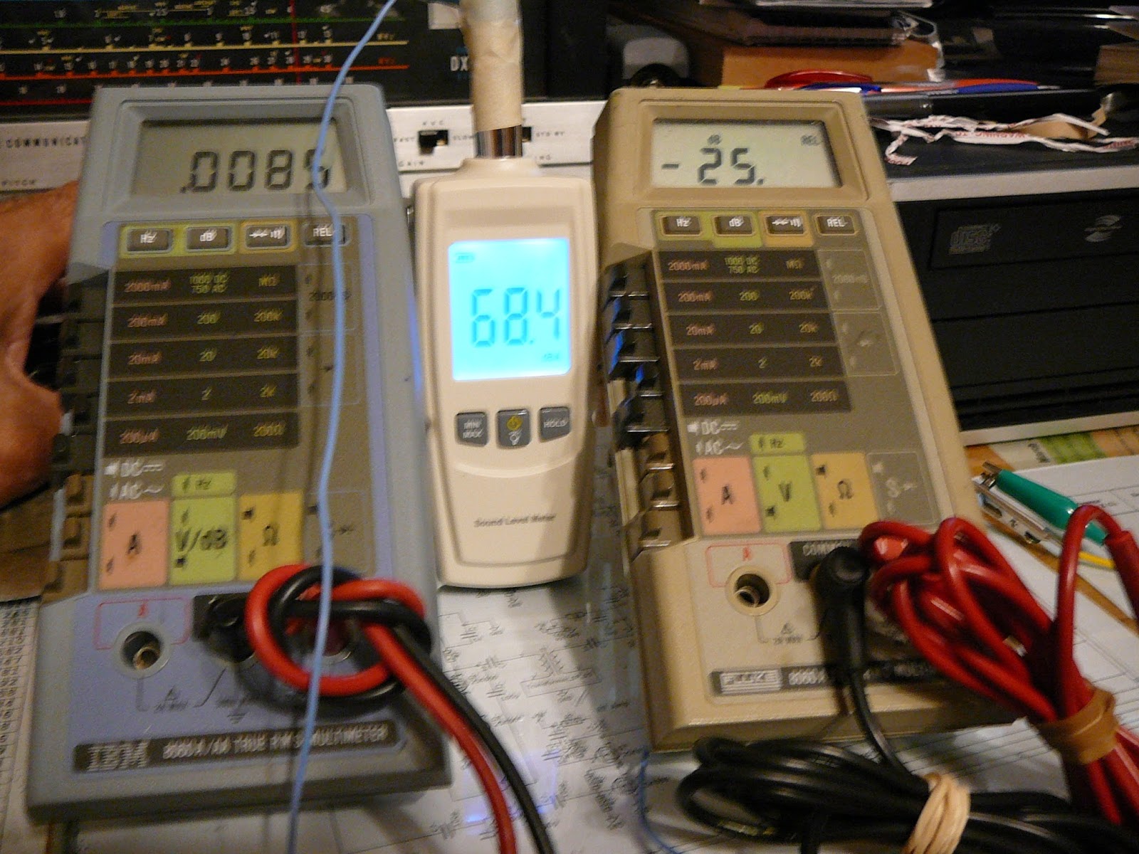
First the high Z tap. How much power would 30mv at 30ua be?Would it be enough to drive the headset?
The same test for R4. I drove my earbud with 1mv and it was load enough.
Now I just need a little shop time for the build.