Friday, February 26, 2016

Spacing a coil from the chassis or shield

 This article is directed at shielding your coil but it also applies to placing it in proximity of metal objects. Transformers, other coils, capacitor, etc.I thought the rule of thumb is to space the coil two diameters away from objects which will effect its inductance. What does the article say?


variable air capacitor #2

I'm posting this for the brave at heart. I did one three plate using two sheets of plastic. Using square plastic I covered half the plastic with aluminum foil on one side and cut a plate from some sheet aluminum in a semicircle. stack the three pieces and drill a hole just above the foil. Solder the rotating plate to a rod that is the tuning shaft. Slide the other two pieces over the rod and put a dab of hot glue on the sides the hold everything together. You can use the blank disk that come in a box of cdrom.

The square coil


The coil inductance is determined by this formulas

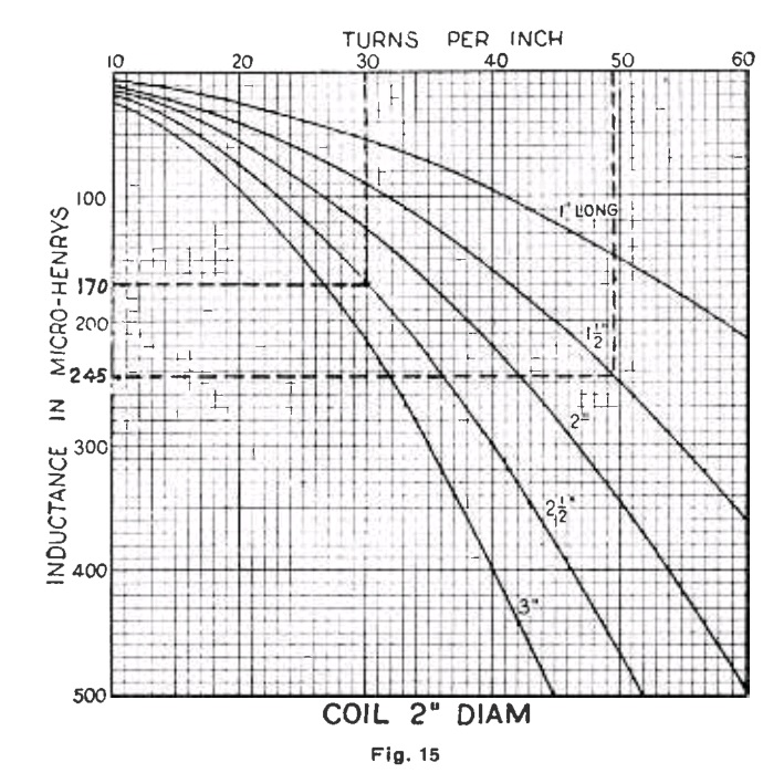
 The factor are length of winding and radius of the windings. K is found from a chart.
 
The Diameter to Length ratio is calculated and then the K is found on the chart. The inductance to resistance ratio is the Q so a larger wire with less resistance or a shorter wire of smaller gauge will give different results. For the rule of thumb a 'square' coil will be the best compromise. There are to many variables to just go square though. For example a transmitter coil may be wound with 1/4" copper tubing.

This example shows the 'square' coil has more inductance with the same size and number of turns the wire resistance will be the same and the Q will be  higher for the 'square' coil. However if the 'square'coil was a receiver coil wound with 24 guage wire and the other coil was a transmitter coil wound with 1/4" copper tubing it could have a high Q so they could both serve their purpose. You could use this chart to find your values.
 
Then determine the Q you want and use this chart to see some posibilities.

The chart shows a larger diameter coil is higher Q.
For more information including spider wound coils check this link

Comparing different coil types


transistor tester

 
I have one of these that still works.  Mine uses a single 1-1/2 volt cell to light the neon lamp. The trannsistor has to oscillate to drive the transformer and light the bulb. The theory is that sometimes a simple ohm meter test will show a bad transistor to be good.

Am Tuner

 
 The capacitors in the base circuit illustrate filtering using capacitive reactance vs frequency responce. The RF is shunted to ground through the .00005 capacitor while the 5 MF capacitor passes the audio to the base. The capacitor opposes circuit voltage change by charging and discharging. The smaller capacitor charges quicker and the can no longer respond. We say they block DC and pass AC and they do. They block DC by charging to the DC level and then they can not pass it. They pass AC only as long as they can charge and discharge.

Thursday, February 25, 2016

Transistor types (50 years ago)


Using one of those former to build a transformer from scrap

 
Ok you make a former and put some wire on it then what? Find some strip material. Banding is good. Next time your at the lumber yard and the guy cuts the bands from a bundle of lumber ask if you can have it. Then cut it in strips to fit your core.


That's half maybe three quarters of the job. It will function but not as efficiently as you would like. It needs some closure around it.
 
 The squares will surround the coil and the 'U' bracket will be the mount.
 
After installing the squares I pushed the 'U' bracket through the core. All that is left is to bend the brackets outward.

Here it is installed on my amp board. I made three. Two interstage and one output transformer.

Why use different size capacitor for bypassing

This video shows how the test was done and gives some explanation.

Youtube video about capacitor self resonance

The question was asked "why use those small capacitors to bypass the power supply when those 100 micro farads are there?".
I used  a dip meter as demonstrated in the video to determined the self resonance of several capacitor. I used them with the leads full length and short. Here are the results of the test.
 
A straight piece or wire will have inductance. The leads resonant with the capacitance and if you go above the resonant frequency the signal sees an inductor instead of a capacitor. This is why you will sometimes hear the old sage advice "keep your leads short.". Here is another problem which is will be hard to find and explain without some understanding of the lead inductance.

We are all probably guilt of this but when you have unexplainable parasitic it is one thing to look for. Inductance is directly related to the amp turns of the circuit so double the current and double the inductance. 


Formers for your coils - antenna coils - transformer

You can make your own coil formers from any thick craft paper. You can use a round core or square or rectangle to fit your need. Plastic tubing and pipe work well. Wood dowel can be obtained in a lot of different sizes. I took a piece of 3/4" lumber and ripped a strip 3/4" wide to make the square forms.
Here are a couple of the ones I've made.
 
For these I'm using a piece of 1" pipe and some "O" rings that fit the pipe snugly.
 
I put some glue on one side of the paper strip and wrap it glue side out onto the pipe. The tightness of this step determines if the coil will friction fit the pipe or slide freely.

I cut two paper rings slightly larger than the pipe OD. Slip one one the pipe followed by an "O" ring on each end. Just a fine bead of glue on the inside at the junction of the tube a ring. You can stack rings and glue them together to get the stiffness you desire.
 
If you need several just keep stacking them on the core as needed.

The square forms are detailed in Babani's book. I'm showing a couple just because I had them laying on the bench. The round one were a magazine cover and the squares were a cracker box. You can use whatever is handy.
 
The same process using some 1/2" tubing.

The coils will slide on the core and go inside the larger. Could be some variable coupling scheme in the making. These are ready for a hot wax dip.  Let your imagination soar and build something!

Antenna coil design - high C vs low C - high L vs low L

 
Assuming we could make our capacitor exactly as we want it. We pick a capacitor that will cover our frequency range without being to 'fast'.  The 50 Pfd capacitor will be difficult to tune. The 1000 Pfd will tune easily. In reality we have to select what's available.

The coil diameter will determine the turns per inch required to obtain the desired inductance. This in turn will determine the Q. More turns per inch require smaller wire which give lower Q.


As you look at this chart you could also consider the 'square coil'. Some authorities say the square coil gives the best compromise for the best Q. 


It's not an exact science because of strays. Stray capacitance and stray inductance will effect the circuit.

Monday, February 22, 2016

An article on RC coupling which counters a lot of common knowledge?


I bread boarded a little amp while exploring the 'sputnick' tube. With 9 volts B+ and 1.2 meg ohm load resistor and it performed well. Still playing with those tubes. They are good prospects for hobbiest.


I'm using a 1.5 volt cell with 16 ohms in series with the filament and a 9 volt B+. This is the power hungry tube in the series. The out put stage in the transceiver.
.