
Wednesday, April 20, 2016
Building a toroid coil
Tuesday, April 19, 2016
Storing a couple of ideas for future projects.

EDIT: This method is easier to provide an air gap. The toroid is easy to install and works well in circuits that don't require an air gap.
Dual gate MOSFET amp prototype.(BF2040W)


The scope is reading the output of the last stage. pretty good signal.


The 4 Volt bus is 3.83 Volts. If the designer wanted he could use a pot instead of fixed resistors but I think it's close enough. Time to find out. I put the coil I made in the unusual IF post and a ear phone on it and lots of rush hissing in my ear. I used a screw driver as a core to adjust and I hear a weather report. I waited for the station ID and it was WWL New Orleans. I ask google and he said I am 135 miles from them. Not to bad my antenna is a test lead clipped to an AC duct.

Examing the datasheet to see what the MOSFET biasing should be.

Next post.
Dual gate MOSFET cascode?


As can be seen the chip has source 1, channel 1, drain 1 and source 2 as one element, channel 2, drain 2.
There are two transistors in series. This is called a casdode circuit. Let's take a closer look at a cascode circuit.

Friday, April 15, 2016


Wednesday, April 13, 2016
How to make an IF transformer for that odd frequency.
Someone ask where to get IF cans another asked what the IF in an antique radio was. They are after parts to build that radio of their dreams. Sometimes NOS is available or a parts only relic which has already seen its last days of service other times it is best to just build your own. One of them was after a 1600Khz IF transformer so that will be the goal. If I were building one to use I would put a trimmer cap on it but this is a demo only so I'll use a fixed cap and get 'close'.
The first steps to inventory the parts bin and find suitable material.
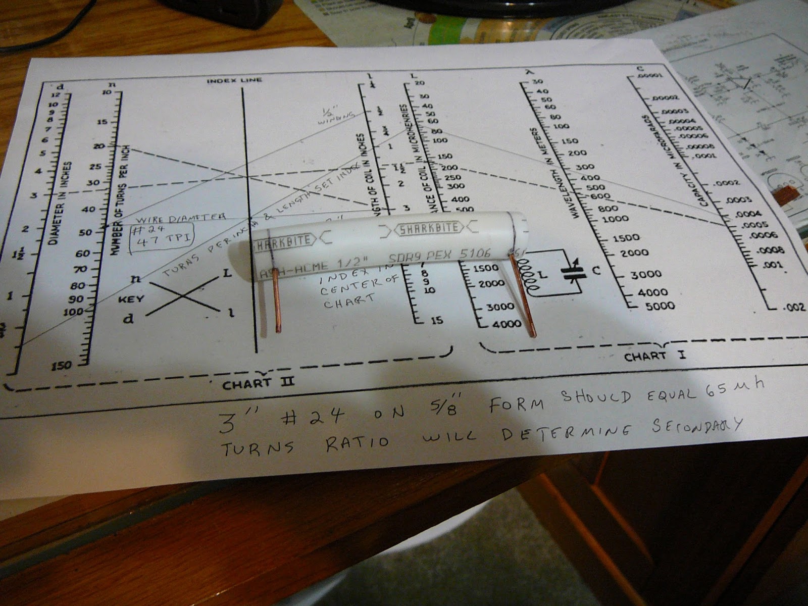
 Look at the chart I can use a core from 1/2" to 12". I was involved in a plumbing project not very long ago and saved some PEX. The 1/2" pipe is 5/8" OD.
 First piece of scrap I picked up is about 3-1/2" long, that could do nicely. Let's try a design around it. I'm using #24 wire which is 47TPI and I'm going with a 3" length. Drawing a line between 47TPI on the second column and 3" on the third column establishes the index. I'm using a 5/8" core so I draw a line from 5/8" on the first column through the index point. This gives an inductance of 65 micro henry. All that is left is to determine the wavelength and draw a line from the inductance to through the wavelength to determine the capacitance. If everthing stays on the chart the design is good. Now to build the coil.
 The PEX uses a locking ring connector so I use one of the rings to mark the end mark. Measure the other end and mark it the same. This is not necessary but it helps keep everything in line.

I threaded a #14 wire on both ends and drilled and tapped the PEX to accept it. Screw the wire in and trim it to length.
 I had to decide if the coils will terminate on one end or both ends. I went with both ends so i put two terminals on each end.

The meter shows 70 micro henry. I wound one coil 3" and the other 1". giving a 3 to 1 turns ratio.

I put a cap across it and feed a signal until the output peaked. Just the first cap I pulled out of the bin. The input was 25 mv with 1.33v out. It could use a slug or a trimmer capacitor to tune it but for now it is a proof of concept.
EDIT:
I started designing for 1600KHz. The frequency meter is displaying 1882KHz. With more capacitance I could achieve the 1600KHz goal.


I threaded a #14 wire on both ends and drilled and tapped the PEX to accept it. Screw the wire in and trim it to length.

The meter shows 70 micro henry. I wound one coil 3" and the other 1". giving a 3 to 1 turns ratio.
I put a cap across it and feed a signal until the output peaked. Just the first cap I pulled out of the bin. The input was 25 mv with 1.33v out. It could use a slug or a trimmer capacitor to tune it but for now it is a proof of concept.
EDIT:
I started designing for 1600KHz. The frequency meter is displaying 1882KHz. With more capacitance I could achieve the 1600KHz goal.
Sunday, April 10, 2016
Dual gate MOSFET - surface mount to leaded


Hats off to Andy again. When I presented the thread on soda straw variable inductor he suggested using #4-40 screw to get fine tuning. The 'rod above is #12 solid copper wire. It's a perfect fit in the #4-40 die.
Tuesday, April 5, 2016
Some more circuits to build with

Dual gate mosfets

JFET radio
Subscribe to:
Posts (Atom)