Thursday, May 31, 2018

AM detector in SPICE


Here I am using 100 MHz. The sim is slow.


I changed it to 10 MHz and it sped things up a bit. So click the link and adjust the components, even remove some to see the results. I used the values from Morgan's book for boys. Simply short or remove the parts declared to be unnecessary and see the effects.

detector.asc

I used LTspiceIV it will work in later versions. Look at L1, C2 and C3 voltage and current. These reading will explain a lot about what is happening in the circuit.


Tuesday, May 29, 2018

LCR meters

You can wind a couple of extra turns on a solenoid coil and the unwrap some if needed but with the basket weave it would be a little more difficult. Following the design laid out by someone else would just be follow the pattern. If you want to do your own and know the value you made you can get a LCR meter is several types. Some LCR meters are made in a case that look like a multi-meter. Some transistor testers have capacitance and inductance meters built in. Here are a couple to look at if you feel the need for one.


The first one is less than $10. The bottom one is less than $50.
There are others, these are the first three my search found. You can also find LC meters. The LC meter would be more accurate and possible a little more expensive. It depends on how many coils you will be winding. It also help ID the unknown capacitor. Some junk box treasures need ID'ing after being hidden in the treasure chest for a time!

the crystal set Mike built - contest winner


crystal radio step 5

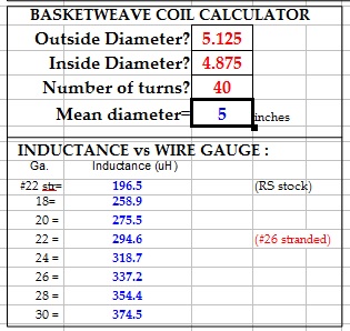
So we could use a 182uh coil. How to make one is the question. Looking back at professor coil we see wire options.  If you set the pins at 5" and wind an over - under wrap the medium would be 5" so I use that for example to see how the turn count works out.


Looking at the chart you see it list a range of wire sizes and calculates the table each time you change the turn count. The table is in standard wire size and you want to use litz so how does that work? Time to look at the supplier's catalog.


Litz catalogue

Go to page 129 for the wire specs. Skipping over the math just look at the wire sizes and construction.

For medium wave you need #46 or #48 wire to see the benefit of litz over magnetic wire or stranded wire. Mike used 660/46. His wire was 660 strands of #46 wire. Now look at more of the data.


To use the data from the calculator you need to know the wire gauge or OD so you can look it up on a wire chart.

Mike used 660/46. The yellow high light 3rd and 4th column. So 660/46 is 1st column - #18 wire gauge equivalent.

So tabulating the results from above:
10T - 23.6 uh
20T - 81.8 uh
30T - 162.6 uh
40T - 258.9 uh
He said he used 182 uh @ 36 turns but he inter-wound a smaller wire which would effect the inductance. The calculator assumes the coil is close wound. In order to get an accurate result it needs the width of the basket (length of coil).
The program uses turns per inch and turns to calculate the coil length. With the interweave we have some room for error. The value given is a measured value the calculator says 218.9 uh. Stretching the coil to insert 18 turns of second coil will reduce the value.

That's about all I know. You should be able to use what you have available and make the coils using the program.
Good luck.


Monday, May 28, 2018

Crystal set step 4

Alan Yates has a some good data I will just provide the links.

Basket weave jig

Using a compass to layout the cords

Thank you Alan.

crystal set step 3

Now let's tie it together. Reactance is expressed as X. The subscript c or l says capacitive or inductive reactance.

With a fixed coil the capacitor is being adjusted to see the effect. At low frequency the Xl is low and the coil passes the current. At some point Xc=Xl and they cancel. The circuit resistance (impedance = Z) is very high. As the frequency increases Xl becomes high and Xc decreases. The coil blocks current and the capacitor passes current. Ao at our radio station frequency we want Xl = Xc. Now back to the calculator.

The example circuit we are using as our pattern used a 182 uh coil so I went with that. Assuming some stray capacitance I use 50 pf as our low setting on the Vcap. The calculator says our resonant frequency is 1670 KHz. Look to the left and it says both Xc & Xl = 1907 ohms. The point is Xc = Xl so it is at resonance.

With the sane 182 uh coil I change the Vcap to 480 pf. We see Xc & Xl = 615 at 540 KHz. So the 182 uh coil in combination with the Vcap chosen wil cover 540 Khz - 1670 Khz as long as we have no more strays than I allowed in the example. If the strays are less we will have a little more range in the adjustment. The next step is to see how to wind the coil.


crystal radio step 2

Resonant circuit.

If the link works it is a parallel resonant circuit.
When you space two conductive plates close together but separated by and insulator it forms a capacitor. Place a voltage across a capacitor will put a chatge on its plates.
When you pass current through a wire it creates a magnetic field. Twist the wire into a coil and it will make a stronger field as the field around the loops aid each other.
Put a coil and capacitor in parallel and pulse the circuit with a charge and the coil will send a charge into the capacitor. The capacitor will send energy into the coil. The cycle would repeat forever with perfect components. In the real world we have losses which must be overcome so the peak will decrease with each cycle.
The Q of a coil is the ratio of it reactance to it DC resistance. This is also the gain you can expect to see in a tuned circuit.
To recap a coil stores energy in a magnetic field and a capacitor stores energy in an electric field. Put them in parallel and charge the circuit and it will oscillate. The frequency at which it does is the resonant frequency.
Next post back to the calculator.

Making a crystal radio - the new project

I'm going to try a crystal radio design. Step by step with the benefit of a design available on the net and some tools also available on the net. The first step is to download the calculator.
Coil design spreadsheet
Read the note on page 1. The author allows sharing as long as he is credited.

The second step is to choose a capacitor. For this design we need a dual variable air capacitor. You could use this one.

The important thing with the capacitor is its range. The one pictured is 20 - 540 pf which is 540 / 20 = 27. The tuning range will be the square root of 27 or about 5 : 1. The capacitor is at its highest value when the frequency is lowest so if 540 pf = 500KHz 20 pf would equal 5 X 500 KHz = 2500 KHz. This is assuming no stray capacitance in the circuit. In the real world we could expect to see 20 pf of stray capacitance. Allowing for that we would see an actual 560 / 40 = 14 and the square root 14 = 3.7 tuning ratio. In this case if the low frequency is 500 KHz the high would be 1850 KHz. This would cover the MW band so would be good to go.
The other supplier's offering is supposed to be a higher quality with a range of 15  - 450 pf. How does the math work out?

Thursday, May 17, 2018

118.5 Mhz receiver butcher

I added two chokes, changed the input  and changed the diode polarity.
Other than that it is as posted on TRB.
The post ahead of this one needed some resistance in the plate circuit and this one needed some reactance. First we get the DC bias correct and then we add the AC components.  Bypassing the source resistor and loading the drain for AC signal conditioning.
EDIT:
I was asked about a good reference. This is where I started:
radio course
The course is bundled in one file. It may take a while to download. 960 pages of electronic data.
EDIT2:
I lowered the value of the coupling caps. Check here to find out why.
Capacitor acts as a coil?

Tuesday, May 15, 2018

Vacuum tube loading -resistive vs inductive

A couple of things to consider about loading.
It is more about current than voltage swing. The slope of the static load line is determined by the wire resistance.


 I measure a 1 pie choke and it is 200 Ohms. Yes it has inductance and resistance.

Saturday, May 12, 2018

Early tube radio schematic and theory of operation

Early radio data
In the old days before schematics had been standardized this is what we had to work with. Actually this book introduces the symbols to be used in schematics in the book.

Thursday, May 10, 2018

How to wind a ferrite antenna

This subject comes up now and then so I am posting the data for when it is needed. Back in the good old days we didn't buy litz wire we made our own . That is the appeal of this unit, it used plain wire (make your own litz).

You need a ferrite rod, some 0.0028" wire and some paper to make formers with. What is this 0.0028" wire?
45 gauge or 0.071 mm. You cut 19 pieces of wire long enough to wind 64 turns and tie a knot on one end. Put that end in a vice or pair of pliers a helper holds and the other end in a drill. Stretch the wire out straight and spin the drill. Gently pull the wire to set the twist in place. You are now ready to make the coils. Cut a strip of kraft paper for the coil former. If you have double sided tape it is good to make formers. Just put a strip of the edge of your pare strip and wrap the strip around the rod with t he sticky side facing out. Fold the strip back at the edge of the tape and trim it with a sharp knife or razor blade. The MW sectionis ready to wind.
The LW former would be made in the same manner and then have an o-ring placed on each end to build a 'dam' to hold the wire in place as it is would.

It's a starting point even if you don't have the ferrite. I have a 6" rod to adapt. I haven't had much bench time lately so I have found a project.
EDIT:
Use the process from this post and make your coil then add the core to make a variable inductor to use with fixed capacitor.
Making a coil for IF or RF
Edit 2: Glue the ferrite to a threaded rod or use a copper or aluminum screw to make this one.
making a variable inductor

With so many possibilities just build something!

Wednesday, May 9, 2018

40/80 update

 This is the Audio Amplifier board. Looks good to me.

The crystal controlled oscillator using a a logic gate. It looks good to me. He said," not much to look at but works well.".  It looks good to me but I'm not a professional builder.
I had these in my folder with the rest of the design and decided to share.