Saturday, March 26, 2016
Designing Resonant Circuits
Inductance-Condenser-Design
This is a link to the 1930s correspondance course that trained a lot of radio men on into the 1970s. How to design resonant circuits with performance in mind.
Radio designers handbook
This is a very large download but is worth the effort if you have a decent internet connection. Radio design from A to Z in this 1500 page book.
Combined antenna coil and V-cap to make tank

Friday, March 25, 2016

homemade selector switch.
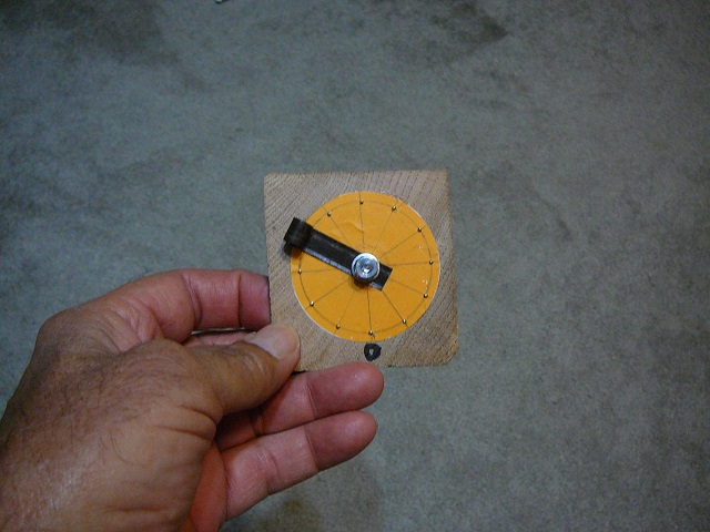

note: The flat metal piece is a spring. Attaching a flattened #16 copper wire under it provides the contact. The spring will work but adding the copper makes a better job of it.
another switch here:
Wednesday, March 23, 2016
Playing with the dip meter
EDIT:
4 diodes
3 transformers
3 transistor amp
dip meter
I did a followup on this with Gilbert cell instead of ring mixer. 6 transistors and two resistors = Gilbert cell.
hearing aid amp using a single cell power supply.

Thursday, March 17, 2016
How to make a frequency doubler
The question was asked. How to make a frequency doubler. Several answers were offered. The advice of one member was one test is better than the advice of one thousand experts. I kind of like the empirical method myself so here we go. What does it take to make a doubler? A signal source. Check i have a dip meter so far so good. A tank circuit. I took an inductor and a capacitor from the parts bin. Check have a tank. A way to clip the input to less than 90 degrees pulses. I have a diode, resistor and a battery. Check can build a clipper. Bread boarded the circuit like this.
 This simple circuit puts a 1.5 volt battery potential across a diode in series with a 10 K ohm resistor reverse biasing the diode. As I drive the circuit my input will have to exceed 1.5 volts and forward bias the diode. If I can the wave forms will look something like this.
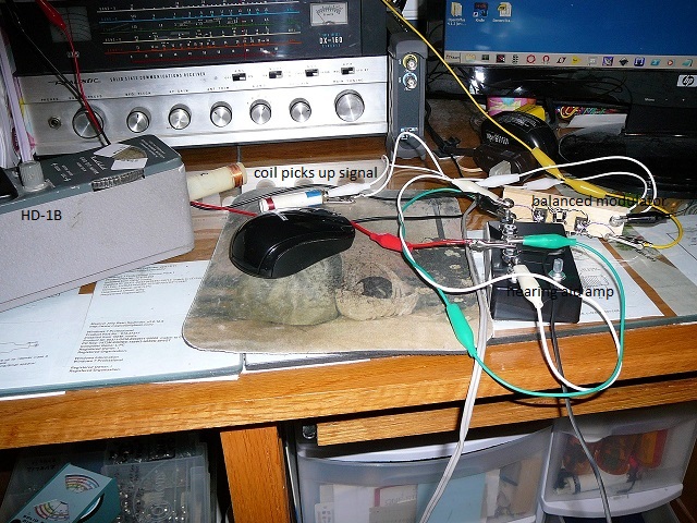
This is actually from a transistorized doubler but the wave forms will be the same. As the diode switches on it will pass the peaks. I hope to get less than 90 degrees. My signal is adjusted by adding or removing loops on the dip meter coil. My test setup looks like this.
 My son gave me the scope and I'm still learning how to use it. It does have a frequency reading at the bottom of the screen. I'll zoom in on it.
 As you can see the frequency is just over doubled. If it were a serious circuit I would tweak it a little. I'll call it a proof of concept and set it aside for now.
EDIT:
The green waveform is not distorted as it seems. Every other peak 'shrinks' as power is drawn by the tank.

 |

EDIT:
The green waveform is not distorted as it seems. Every other peak 'shrinks' as power is drawn by the tank.
Needed a toroid for an antenna tuner
I heard back from Andy that he had made a modulation transformer using the banding material as I had posted. The only problem I had with that method was the material being spring and just wouldn't stay in the shape I wanted. A tip of the hat to Andy. He suggested I could use a torch to remove the temper and make it more managable. It worked like a charm.
I wanted to make an antenna tuner and didn't have the toroid. Once I softened the banding winding a toroid was a piece of cake.This is what I needed.
 Here are the finished toroids.
 I got 1 millihenry overall and about 50 microhenry between taps on the larger one.
I wanted to make an antenna tuner and didn't have the toroid. Once I softened the banding winding a toroid was a piece of cake.This is what I needed.


Wednesday, March 16, 2016
One transistor radio signal paths
This circuit provides a good example of
the different component functions.
First the antenna, coil, and ground
provide a signal to the receiver but that's not all. The coil
provides a DC path to prevent static charge building on the antenna
and is a high resistance path for high frequency signals blocking
them from the receiver.
L2 and C1 are a paralell resonant
circuit. They select the frequency that the set will receive and give
it a voltage boost.
C2 is a low resistance path for RF
signals. The output is being developed across R1. High frequency RF
bypasses through C2 charging it quickly and low frequency AF go
through R2 producing a voltage drop. The voltage dropped across R1
equal the RF peaks while the voltage across R2 is developed as C3 is
charging.
This leaves R3 and C4 which form a
filter to allow the DC component to flow back to the battery and the
AC component to return to the FET source. R3 must offer enough
opposition to the RF component to make it see the C4 as the low
return path. Bias on the FET allow a space charge to build in it. As
the input is impressed on the gate it modulates the FET channel
current and develops the RF across R1 which in turn supplies a charge
signal for C3 and develops the AF across R2 which powers the phone.
The question is how many paths are
there? The battery is providing a DC which is fairly constant. The RF
and AF components are source to drain and back to source bypassing
the battery through C4.
Subscribe to:
Posts (Atom)