Wednesday, May 25, 2022

Feeding the receiver. Combining the last few post. Artificial ground increases receiver output.


Using my new (to me) Emerson as the example. The new set is a couple years older than me, about as old as dirt!

Anywho look at the antenna coil. It is a spiral connected to the input circuit in parallel with The tuning capacitor. The parallel circuit presents a high Z to the input.


The actual loop antenna looks something like this.

Look at the dotted line in the schematic. This is a single loop primary for the external antenna to connect to. When you attach an antenna and ground to the loop it will be a short circuit and have the highest possible current through it. Notice the 2 screws (center left). They are the antenna and ground connections. If you want to really soup up the receiver you could add a loading coil or artificial ground to the input loop.


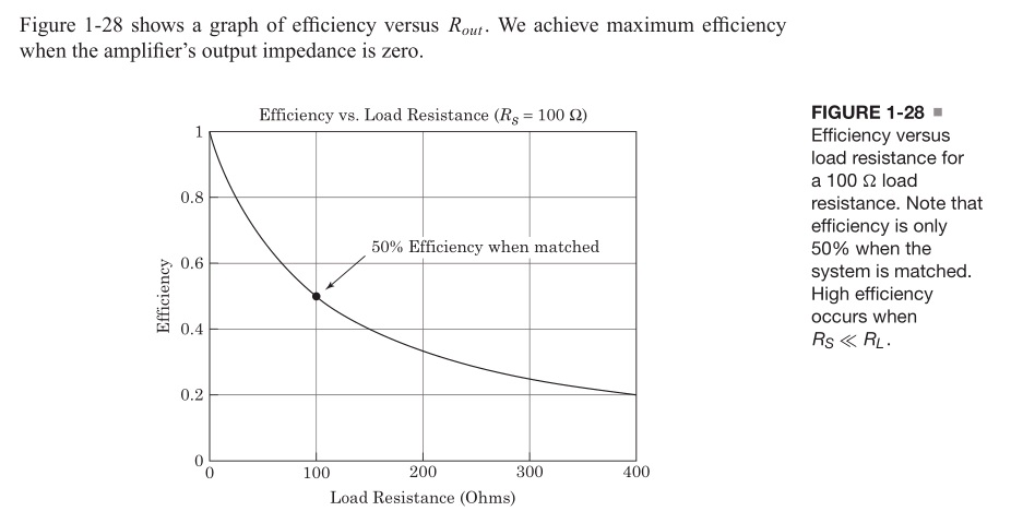
Suppose you have the input loop forming a series resonant circuit which is feeding the parallel resonant tank in the converters grid circuit. The series circuit presents a very low Z and allows max current flow. The parallel resonant tank presents a high Z with minimum loading on the antenna. Remember from the last post the highest power transfer is when Rin << Rload. A short feeding an open would be ideal.

My car radio will find 2 or 3 stations when I scan the AM band.

This old set finds stations from one end of the band to the other. 

 NOTE:

A little extra data while it is on the screen. Look at the filament circuit. See the pilot lamp in the filament circuit? It serves more purpose than lighting the display. The notes give 2 sets of reading. One with and one without the pilot lamp. The lamp burned out while I was working on the set and it happened as they said it would to cause the circuit reading to vary.

I point this out because we had this discussion an the radio board before and the experts denied the facts as presented here. The notes and real life test agree.


Friday, May 13, 2022

Another look at power transfer.


Note high efficiency occurs when Rs<<Rl.

P = I^2 * R therefore low Rs = low lose and high Rl = higher power out.

 Simple enough with resistive  circuit.


Now consider the AC circuit. ONLY resistance consumes power. Reactance absorbs and releases power. Z matching does not means setting the input and output equal, unless we want to lose half our power in the source. 60 years ago we would neutralize a circuit which meant adjust for phase shift. Reactance produces phase and imaginary power. Zero phase shift means resistive load and true power dissipation. So neutralize the circuit and set the phase angle to zero to get power transfer.

60 years ago neutralize the circuit. Today conjugate the reactance.  In neither case are we setting Ri = Rl.

Food for thought.

In the last post I said "TUNE" the ground and "TUNE" the antenna.

Would be better to say NEUTRALIZE the circuit reactance.

R + i0 feeding R + i0 provides maximum power transfer. 

Low R feeding high R for best efficiency.

Years ago the device was named a tuner and that is how we describe it. 


Tuesday, March 8, 2022

Artificial Ground or Tuning the ground or neutralizing the reactance in the ground loop.

 The antenna tuner can have a section to tune the antenna and a section to tune the ground. You can search and find several commercial products and some created by hams. They are mainly for transmitter applications but could help a receiver too. Some popular home brew sets have tuners with matching. Anywho I assembled a little monitor and ran some test on my 7 foot whip using the chassis ground on my DX-160.


It is fairly simple but does a good job. I am using the NanoVNA to sweep the circuit but you can use a signal generator. The sweep allows the operator to see where he is on the curve a fixed frequency will require a little searching. 


The antenna lead is simple threaded through the core. The core was from a core test. It was wound and tested to see the core properties. I did not count them but about 15 - 20 turns. I did measure to coil. It is 100uh. The meter is set to 50ua. You could use a DVM set to its lowest range. Use the pot to adjust the reading. (keep it on scale)


This is the circuit I used. The blue is RF. The lighter trace is DC output.I am using nanovna-saver to control and monitor the test. The program attaches to the vna, displays and records data. In the following shots I tested the whip against ground and then added a Vcap in series with the vna and ground. You will see the dip shifting as I change the Vcap setting.


When I have more time perhaps a dual circuit to monitor the antenna and the ground?  

Tune the antenna with a PI network and the ground with a series LC?

That would require 3 or 4 Vcaps and some tapped coils. I thinking a simple arrangement would consist of 3 or 4 (yellow/white) cores with 1T, 2T, etc. and 3 or 4 (green) cores with 1T, 2T, etc.

I did a test board with 6 green cores and found the following reading at the taps.

1- 2.5uh

2- 12.8uh

3- 29.8uh

4- 68.7uh

5- 133uh

6- 213uh

It could use a switch or simply a clip lead to select the tap.

Um? more on that later.


Tuesday, February 22, 2022

simulators can be fun but...

I have been using EZNEC in WINE on a linux box.

 https://www.eznec.com/

It works quite well but the screen size is to small for my ancient eyes.


I did a screen shot and enlarged it. The red note says the wire segment is to long. Note wire 2 Y = 70 feet.


I shortened the wire to 60 feet and the red went away. Looking back at the first comment it says segment to long? Now look at the last column. 2 segments. I changed it to four and set the wire back to 120 feet. All is well. It would help to know some function running the math? Apparently the wire is divided into segments as part of the calculations?

Anywho here is the screen shot from Xnec2c ( the linux version of NEC).


I learned something if I can remember it. Get the magnifier and read the comments carefully.

Thanks to Andy for the references to 

nanovna-saver andSimNEC.

I downloaded and install both. They work well under Ubuntu.

I connected the nanovna to a 2 meter wire clipped to an ac register and the programs connected to the vna and displayed the antenna response.

They are fun to play with but will have some learning curve.

A sample shot from  simNEC. 


It plots the response and you build the network by simply click and drag.


Z matching is not all to be concerned with

 How would you connect a dipole (balanced system) to an unbalanced receiver? Problem is the dipole is not grounded and the receiver terminal is.

The balun not only overcomes the grounding half the signal problem it also add common mode rejection. As that antenna lead travels down from the attic it is subject to various noises. Terminal 1 and 2 feed the signal out of phase and the transformer passes it to the secondary. Noise arrives in phase and the center tap of the transformer disposes of them without any going to the secondary.


Monday, February 21, 2022

Z matching continued...


Motorola app note

Motorola AN-0721 Z matching RF amps. The place to start

 volume one

Volume one of two. 526 pages of data to start the journey.

 Volume two

Volume two of two. 576 pages of data to continue the journey.


Wednesday, February 16, 2022

Z matching part 2

If you read the first part of the tutorial I linked in my last post this may be your uh hah moment. I will post one sim that tells a lot about web wisdom and reality. It will also lead to more questions. I hope to do another post to continue the story of Z matching. The journey continues.


In the simulator you can set the generator Z and it will not be displayed. For this sim I set the internal Z to zero and placed a 50 ohm resistor in series with the load. Remember Power is equal to current squared time resistance. In both cases I have the same load so the power increase or loss is a square function. I(r5) is more than twice I(r2) so the power delivered is more than four times as much. Look at the voltage delivered to the loads. V1_out is one half the generator voltage wish tells Zg = Zl. Web wisdom  states max power transfer is when Zg = Zl but they do not finish the story. The tutorial begins with that as the first step on the journey. The second step is to understand the power loss internal to the generator is one half of the available which is not acceptable. 

1st step = Max power transfer Zg = Zl

2nd step = The generator is going to at least waste a lot of power and possibly smoke

3rd In some cases the power transfer is more efficient when a PROPER Z mismatch is used.

Years ago we were taught to use a MINIMUM of a ten to one ratio.

Later they said we should use a MINIMUM of 100 to one.

When do we really need be concerned about matching and how do we apply the matching for best advantage? 

To be continued ..........


Tuesday, February 15, 2022

definitive tutorial on Z matching ( 70 years ago )

When I took this course in 1960's it was state of the art. It is a little different today but the basics will never change. That said if you study this little 40 page tutorial you will have the basics for Z matching far beyond the one line continually misapplied. Many an expert will tell you that one line and stop. It is not meant to be the definitive statement but rather the teaser line that draws you into the study so either ignore the post or be prepared to study at least the first 5 or 6 pages. If you read the first page and say "that is what the other guy said." you will miss the point. It is the lead in not the final statement. So for the brave download and read the document.

Z Matching


Antenna data


Sunday, February 13, 2022

Antenna tuner data

 Just putting this here so I don't misplace it. It matches a low Z transmitter to a high Z load.

When feeding a high Z (100k's - meg ohm)receiver input circuit from an antenna with relatively low Z (less than 5K expected) could we benefit from this matching. Matching in order to produce loading in a transmitter and matching to produce maximum signal transfer in the receiver. 


Wednesday, February 9, 2022

Antenna matching in sim

 In this series of shots I have the generator representing the antenna (signal). The Tline represents the coaxial cable. The load resistor represents the receiver. If you examine the series you will see matching for maximum signal to the receiver does not mean making the impedance's  equal. 

Two things to observe.

1. A minimum of a 10 to 1 Z ratio is better than Zi=Zo.

2. Reactance is our enemy. With resistors things go smoothly. Adding reactance upsets the apple cart.


In the last shot it could be said I did a conjugate match.

It may also be said I neutralized the reactance to make a purely resistive circuit.

In the antenna circuit power may be measured in nano watts and voltages in micro volts. With a low (less than 400) ohm source and a load of several KOhms the voltage is what counts. A reactive source reduces the voltage. 

Food for thought.


Tuesday, February 1, 2022

inverted VEE antenna

 Was looking at Cap top hat and came across this.

 Storing it here.


Inverted Vee


Monday, January 31, 2022

Proof of concept.


Yes. When I allowed for strays everything fell in place.


It is in how you figure?

 If I have a 200uh coil and I want to tune 1-5 MHz what value should the tuning cap be?

1MHz     2MHz    3MHz    4MHz     5Mhz

126pfd    31pfd     14pfd    8pfd       5pfd


Now if I mark my dial the scale does not match my Vcap values. Why?


Notice the only place it is close is with the hi value cap. The lower the cap the more the strays effect the circuit.


When the dial does not match we can measure the cap and calculate the inductor value.


1MHz     2MHz     3MHz     4Mhz     5MHz

129pfd    34pfd     17pfd      11pfd     8pfd

196uh     186uh     165uh     144uh    127uh

If we do not account for the strays it appears the inductor is changing value.

Maybe another series of scans with the adjusted values is in order?

Friday, January 7, 2022

RC transmitter in sim


 The multivibrator chops the RF signal by switching the darlington pair on/off. The Darlington supplies power to the oscillator.


The antenna is open circuit and the standing waves are there but you can see the switching.


Placing a resistor for the antenna produces a cleaner out put.

I have no data on the antenna. Something else to investigate?


RC transmitter from Radio Constructor mag Sinclaire ST140 ST141

 I am just putting this here before I lose it. I am locked from TRB again. A new member asked about Sinclair transistors.


It works in the simulator using 2N2222 and 2N3904 transistors and 1N914 diodes.