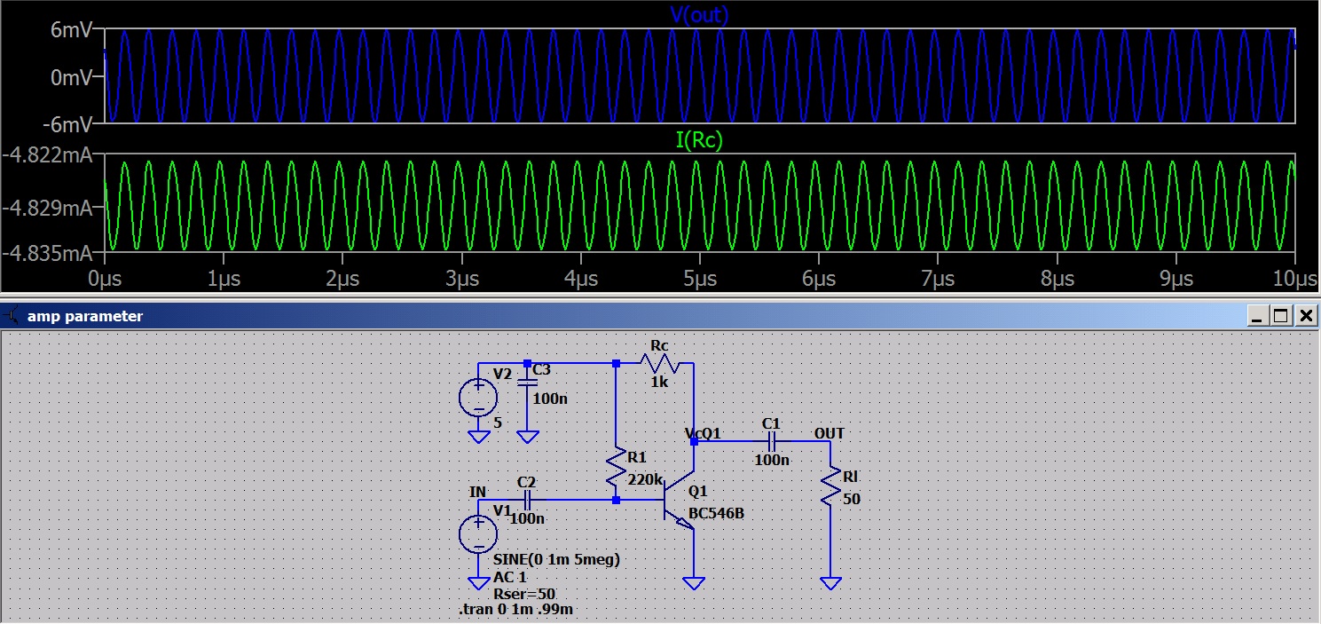
The "rule of thumb" is that the output of an amp is equal to Rc. If this is so then making Rl = Rc will give the Z match for maximum power out. We need to consider is the transistor a voltage amp or a current amp. You can look at it as a voltage controlled resistor OR a voltage controlled current source. We need to consider the frequency and the need for stability too. I generally like to make low voltage and low power circuit to operate on battery power. This influences the design too. First a series of screen shots to consider.
 |
| Here I set Rl = 10Rc. 80mv output with 1mv input is reasonable. Look at Ic and RQ1. |
 |
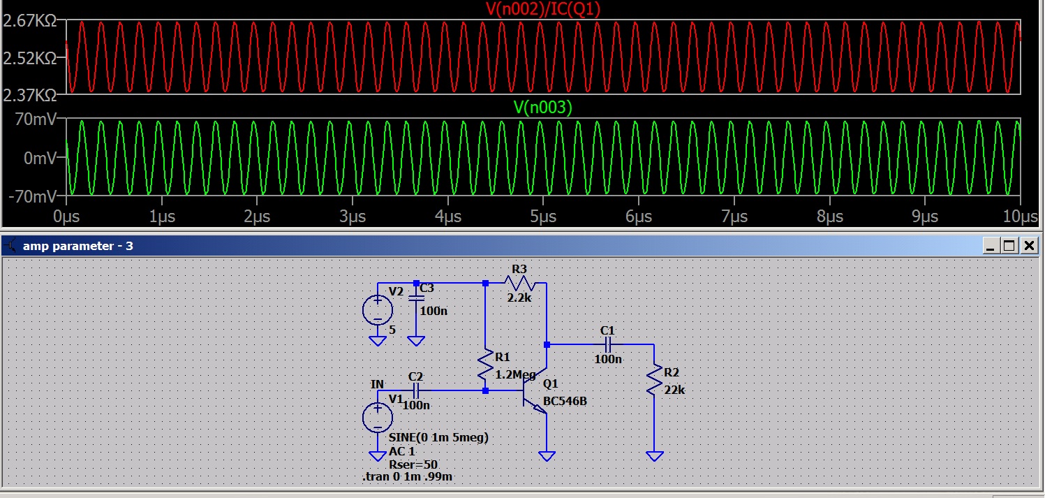
| I set Rl = 10RQ1 the power output increases. What's up with that? Vout is unchanged so it must be a current change? |
 |
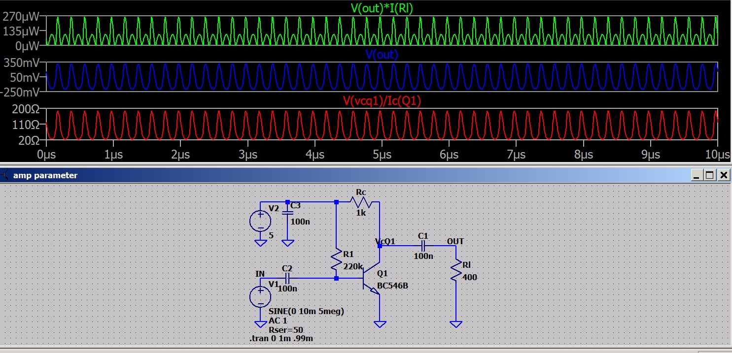
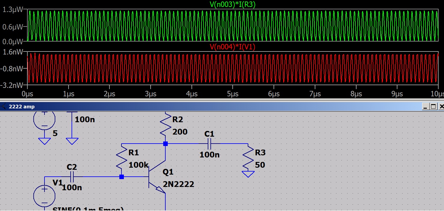
| I set Rl = Rc and get the higher output. It appears making Rl = Rc gives a higher power output and making Rl = 10Rc gives a higher voltage. |
|
 |
| Wait a minute! setting Rl = RQ1 gives a higher power output than when Rl = Rc? |
 |
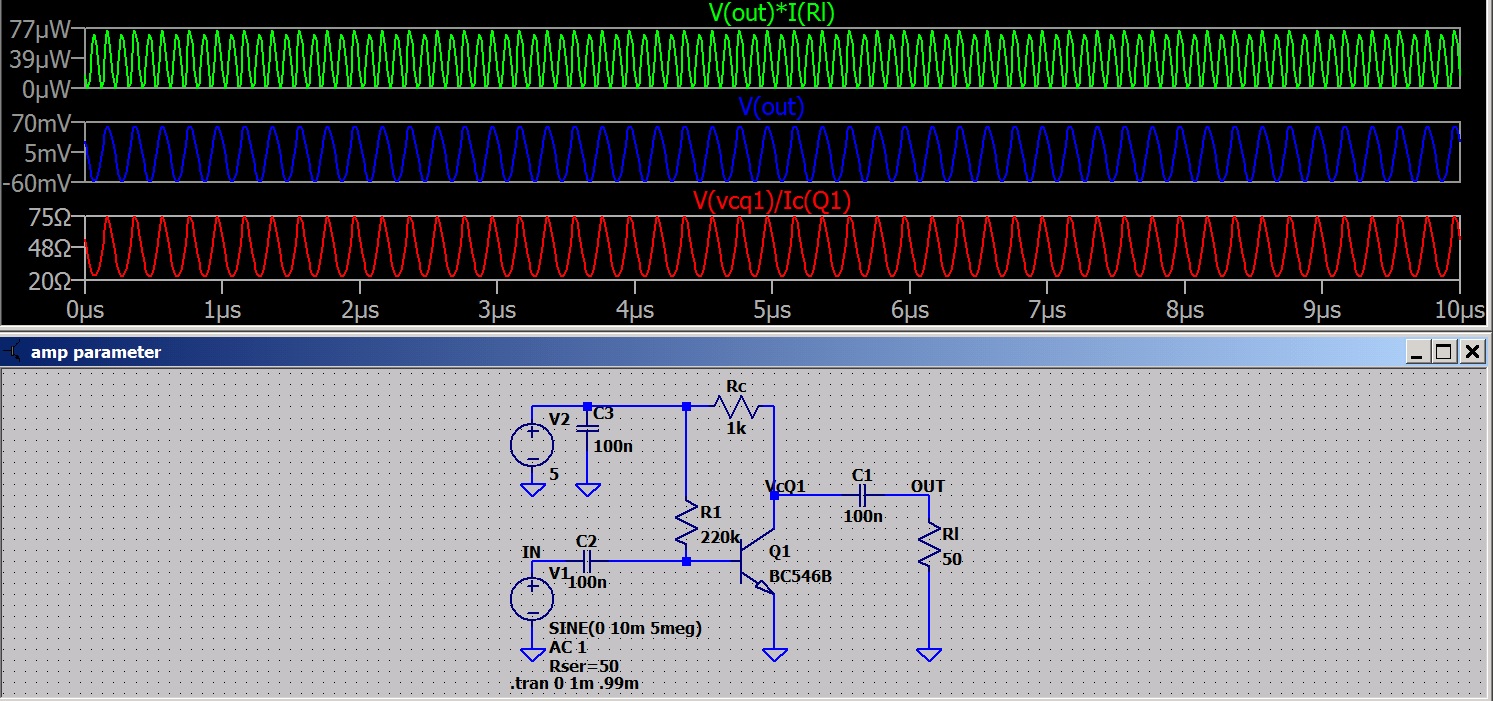
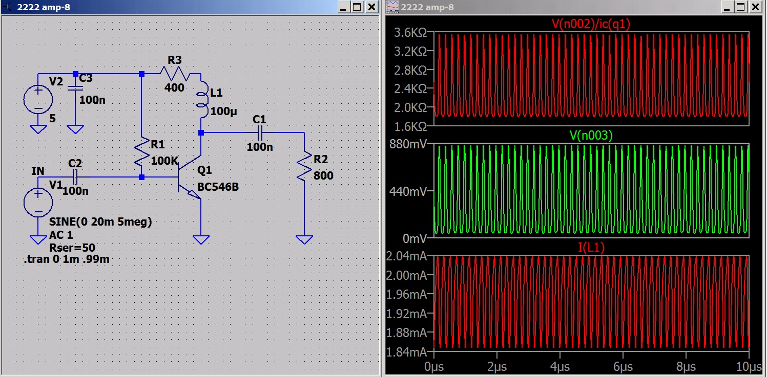
| I set Rl = Rc / 10 and raised Ic to 10ma. More power out. Note Rl is about 1/10 Rc. Look at RQ1. So it is becoming more obvious that for voltage gain we want a high Z circuit and for power gain we want a lower Z circuit. |
 |
| In the previous circuit the transistor was dissipating half the power. This one is producing more output without heating the transistor as much. |
|
|
How much Ic do we want. The last two shots have the same power out BUT one is 10ma and the other 50ma.
Some food for thought?
Edit: Look at some RF 50 Ohm amps and you will find most run at about 10 ma Ic. This seems to be the compromise for Z matching and power consumption.
Audio systems were designed for 600 Ohm allowing lower currents and power consumption.
At RF the lower Z helps overcome circuit reactances. In a microwave circuit a wire running a fraction of an inch above the ground plane will have inductance and capacitance and the circuit is more critical. I'm working in the HF range which is more forgiving.
As I said food for thought.
 How much Ic do we want. The last two shots have the same power out BUT one is 10ma and the other 50ma.