Wednesday, January 30, 2019

Hybred as built

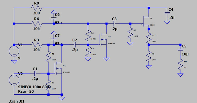
It was to sensitive and need some high frequency attenuation. I connected an antenna and could adjust the pot to a point I would hear radio signal. The pot adjusting the JFET into pinch off would detect an AM signal. I put C6 and C7 in the drain circuits to bypass the high frequencies.
My AF signal generator would drive the amp to hard with the output set to minimum even with the 20db attenuator switched in. After adding the bypass caps I can adjust the pot from min to max without it breaking into oscillations with an antenna and ground connected.
Without the filter it has high gain through the MW band.
With the filter the roll off is well below the MW band.
The AF response is good for my ears. The filter could be adjusted to modify it to suit.
I used a 2K pot for R11. It pinches the JFET off at about 50% adjustment. A 1K pot might be better, I have some 2K's in the junk box and used what was on hand.
C6 and C7 could be 1n to 100n. The larger value will give more bass boost.
EDIT: R11 is a 2K pot used to adjust the J112 bias. It will pinch off the Jfet at about 1K. You could use a lower value.
Tuesday, January 29, 2019

Hybred Amp MOSFET input JFET output

This project is to use MOSFET and JFET amps. It works so well in sim I will have to assemble one. First the circuit.
R11 is the volume control.
I'm swinging R11 from 1Ohm to 1KOhm. With 100uv in it will rattle an earbud.
The frequency response and gain thru the AF range is good.
Time for a build.
EDIT:
You could use 2N7002 and any general purpose JFET. The 2N7002 should be a direct sub for the MOSFET. Might need a larger source resistor with a different JFET. If R11 is 5K or 10K it should work with any JFET.
EDIT2:
I used a 2KOhm pot for my build.

Thursday, January 17, 2019

Looking inside the transistor

Let's look at the load vs output.
 10 ohm.
20 ohm.
30 ohm.
40 ohm.
 10 ohm
20 ohm
30 ohm
40 ohm
Now a look inside the transistor.
Here we see the emitter current and the voltage drop from emitter to collector. R=E/I is the yellow trace. The transistor Z is about 4K. It is a dynamic value which changes with bias.

Wednesday, January 16, 2019

Screen shots of the low Z amp

I stepped R to see the effect the load value had on power output.

With a higher load Z the output is nW.

The 50 ohm load receives uW's of power. The amp supplies higher output to a lower Z. The 470 ohm resistor is for biasing. The AC impedance is not equal to 470 ohms or I would get max power transfer at 470 ohm. What is the AC Z???


Monday, January 14, 2019

Low Z power amp feeds an ear bud

I made an amp with a transformer on the output which works well but I thought I would build one without the transformer too. The problem is the common emitter low Z amp requires more current than I care to draw from my battery. The best choice would be a common collector circuit. It would look something like this:
When a circuit like this was asked about on the radio board the board experts declared it was a power hungry waste of time and money. To test the theory I will display the circuit current draw and power gains. First the instructor said,"set the DC circuit values and then add the AC components."
I established a current drain of about 1.25ma. I could turn the generator off and see the DC but it's good enough.
In this shot the green trace is the emitter current (the 820 ohm resistor) and the red is the ear bud. Without C2 the voltage drop across the emitter resistor would cancel the input and we would see little gain.
The circuit is producing about 9nw which would drive my earbud to a good volume.
I set the generator to 300hz which is my low frequency audio.
The green is the generator and the red is the earbud current. You can see we have no voltage gain but quite high current gain. Since power is I squared * R, a current gain of 2 would equal a power gain of 4, a current gain of 3 would equal a power gain of 9, etc. This should clearly show the DC and AC should be addressed separately and the circuit can function as a low Z amp without drawing the battery quickly.
The cascode amp using this stage as its output and a voltage amp as its input would be the next step in the progression. maybe next time?

Monday, January 7, 2019

a pre amp build and test

If you have followed my blog you will realize I like circuits that are easy on the battery. So I may sacrifice a little performance to conserve battery. With this in mind look at the sims with different load resistors. While low Z circuits require higher currents we can sometimes use lower current and still get reasonable gain.
 This is the circuit as designed. 8mv output but draws 7ma.
with a 2.2k load we get 6mv with 3.4 ma battery load.
with 3k load we get 5.4mv out with 2.5ma drain on the battery.
With a 10k load we get 2mv at less than 1 ma drain. If 7ma drain is good with you the first circuit will be good for you. I like the 3k at 2.5ma draw. I have some 3k in reach so that is what I used. Let's look at the circuit.
The yellow probe is on the input and the green probe is on the output. Both traces are on the same range.
I increased the signal so the yellow trace would display a curve. I had to increase the range for the green trace. It is giving a good boost to the signal. The test was at 4Mhz. I sweep the signal to about 10Mhz and down to 100Khz. As would be expected the signal was stronger at the lower frequencies. It is impressive for so simple a circuit. 1 transistor, 2 capacitors and 3 resistors. Using surface mount components it can be made very small. I have some 1/2" tubing to try and mount an amp in. It will be easy enough to mount on a small piece of board or glass. A microscope slide could work well. Mounting a connector will be the challenge. The tubing is the same size as a BNC connector. It could be swagged to make it work. An altoid box may be better. with a divider it could hold two amps.

amp in a pipe - self biasing examined

This is the basic idea. I have made a couple on a breadboard and they perform well. I think I could use 2 for preamps on my scope and make it more useful. The low range is in milli volts. With the amp I could read micro volts. That's the plan.
node 3 and 4 are either side of R4 and node 6 is the output. When I measure node 4 and divide by the current through R4 it give me the input Z. It is a dynamic reading so we have to take the average. 150 ohms ? Basically the base emitter junction and Xc1.
I have some surface mount 2N3904 for this one. The arrows point to nodes 3, 4 and 6. I'll be taking reading from these nodes to determine the impedance and gain.
It look good.
I measured node 4 and divided by I(R4) to get the input Z.
I cleaned up the chatter from the previous shot.

The larger capacitor charges and holds the voltage to make it appear that we have a negative resistance. It is the phase shift through the capacitor.
In this shot I moved the reference to one side of R4 and measured across it. The floating ground allowed noise to display but the 50 ohm resistor is showing.
Here I leave the reference at R4 and measure to ground to get the input Z. When I did the same measurement with a 1000u cap the reading was negative. The 100u cap show a positive reading. The RC time constant is determining the reaction to frequency.
Back to the original circuit.
Here we see the 50 ohm generator Z
If I had Zgen = Zin I would read 50uv with the generator set at 100uv. How would I adjust that? Does it need adjusting?
100uv in and 7000uv out. The Zin could be adjusted by changing Ic. This could be done by adjusting the base emitter resistor or the load resistor. Changing either one would vary Vc which in turn would change Vb and cause a shift in Ic. If you plot a load line you would see the circuit gain changes with slope. So making either resistor adjustable would allow the gain and Z to be varied.
Zin is low so this would be a good circuit for a 50 ohm system. It would load a high Z circuit. Why use 50 ohm? A good question that could use a good answer. Maybe a topic for another time.