 |
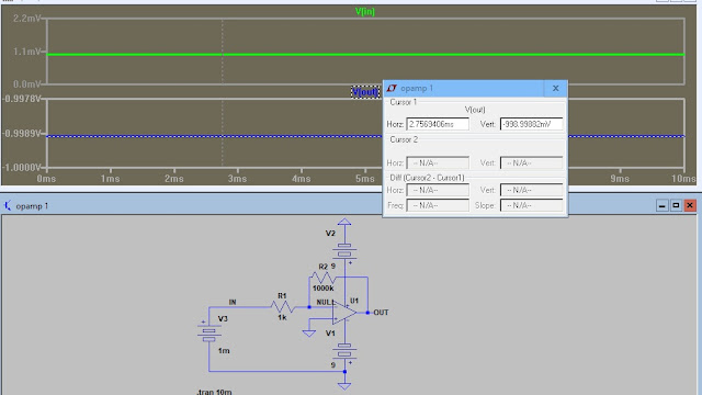
Using the opamp design as our basis we would expect a gain of 100 with the 1k to 100k feedback bias network and we expect 50mv out with the load matching the source Z. Q1 load of 4k7 matching R4 delivers that 50mv. This is a very useful circuit and fairly easy to design once you learn the design considerations.
|
As stated in the opamp design I would expect the output to be 100 with the load set at 10 times the R1. What happened? Remember the opamp is capable of a gain of 100,000. The transistor is limited to a much lower gain. R3 is setting the base current which in turn sets the gain so we need a little more consideration in the component values.
I reduced R2 and increased R4 and the gain goes to 200.
Matching the load brings the gain back to 120.
Increasing R2 gives the desired gain of 100 with the load matched.
Here we see the frequency response for the circuit. Adjusting the capacitors will give the response we need.
What can you deduce from this series?
Can we adjust the input Z by adjusting R2?
Can we adjust the output Z by adjusting R3?
A low Z circuit is high current and a high Z circuit is low current. Can we design the circuit to be voltage or power gain? For voltage gain would you want high or low Z?


