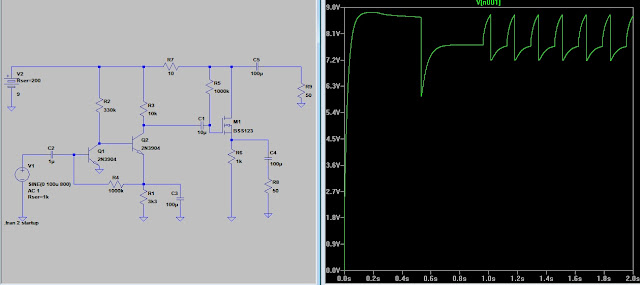
Added C3 on input to modify the response.
Monday, March 29, 2021
Sunday, March 28, 2021
Monday, March 22, 2021
Friday, March 19, 2021
Emitter bypass cap
When you begin to analyze a circuit the first step is to open the caps and short the coils. Then analyze the DC paths. Establish the bias to determine the Q points.
The AC function can be seen by adding the caps and coils back in the circuit. If you build a sim with no caps and then add the AC signal you will have degenerative feedback developed across the DC bias components. Build an alternate AC signal path with the caps allow the AC impedance to be different from the DC resistance.
So remove the bypass and look at our circuit.
The circuit is functional. It produces a good signal. (faithful, linear )
Not put the bypass back in.
We get a higher gain but the signal is less faithful.
You can remove the source bypass and get the same results.
We see builders who make (regenerative) receivers with audio amps. (or so they say)
If you have a strong station in your area you could connect an antenna to the input and receive the station. Is it a regen receiver?
Consider this before answering.
As the circuit was first presented you would have some 'drain bend' which could allow it to be used as a receiver. Try adjusting the source bypass and see what happens.Thursday, March 18, 2021
A series with mods to the grounding and size of drain cap
 |
| Setting the probe to reference the drain. With the sim running click on schematic to open the menu. |
The point I want to make is the drain and source caps are 'juggling' the current. One charges as the other discharges. If they are small they limit the current. Set them to 25ufd and see what difference it makes.
A quick look at RC time constant
Wednesday, March 17, 2021
Wednesday, March 10, 2021
more balanced current
Compare the current through R8 and R9. Increase R7 to get a more balanced current.
Trace the current paths during a cycle. One cap charges as the other discharges etc.
How does this effect the current through R7?
How can we improve the circuit?
I disconnected the input to see what happened.
It appears I did a great job of building an oscillator. What did I do wrong OR what can be done to improve the circuit?
Vary the battery resistance and test the circuit stability.
Add 2 Ohm internal resistance in the battery, click the battery and you find two boxes voltage and resistance. Run the sim and you see a swing in supply voltage. Increase the battery resistance to 200 Ohm.
Wow!. The supply drops to less than 8 volts and it oscillates. (motorboat)
The layout to avoid cross currents in the ground plane.
When examining the circuit stability current loops could become and issue.
Tuesday, March 9, 2021
Adding the .startup command will cause the circuit to start with 0 volts.
I set the scan for 2 seconds so the circuit could stabilize.
So this is what happens while the capacitors are charging.
The battery resistance is at 0 ohm. When we add the battery resistance what effect will that have?
I saw a recent post that said the bigger the caps the better. This series of post will explore that idea.
So the idea is to look at what we have and vary the circuit to get a better response.
I put this circuit on a board and it was quite sensitive and quite unstable.
We need to consider the battery resistance. A fresh 9 volt battery may have 2 Ohms internal resistance. As it ages that may go much higher. How to look at the battery resistance will be coming shortly.
Earbud Amp with feedback ideal circuit
This ideal circuit would be great for my earbuds IF it works as the sim does. I have some 10ma earbuds which it would be good for. Next I add a real world test.


