A couple of band pass filter designed by ELSIE.
I ask ELSIE," what about those odd coil values?".
She answered."Air coil or toroid?".
I said,"Both!". (When you don't understand the question bluff.)
She gave me these answers.(She did ask a couple more questions, former size and such.)
Friday, January 12, 2018
Monday, January 8, 2018
The DIT's first radio
Here is the circuit:
Do you see the design flaw? (hint:the diode is backwards.)Here is here build:
You see the variable capacitor? From the looks of the station marks it is pulling in some signals!
She's already planning her next build. It will include a 2 transistor AF amp driving a speaker. The wood is to be replaced with some plastic.
Great job kiddo!!!
Saturday, January 6, 2018
Lambda powered DBM with hearing aid amp
This is my best DBM radio to date. The clip lead center top is the antenna. To project box on the left houses the Lambda Diode Oscillator. The red jack accepts the coil. The large grey knob is the tuning cap. The two terminals on top of the box receive 3 volts from the battery through a 1K pot. The two terminals on the right side of the box are the output. They are fed through 1 to 9 transformer. I simply passed the diode ground threw a core with 9 turns on it. The block in the center is the DBM. Two transformers and 8 dual diodes were used to build the DBM. The project box on the right houses the hearing aid amp.
hearing aid amp
If you look at the second picture on this link I am making the diode ring.
The DBM diode ring
This one uses 8 surface mount dual diodes. I put two on a side and paralleled the four diodes.
hearing aid amp
If you look at the second picture on this link I am making the diode ring.
The DBM diode ring
This one uses 8 surface mount dual diodes. I put two on a side and paralleled the four diodes.
high gain amp - to high?
The circuit that was offered.
I like to use connect the dots to do the hook up so First thing I did was number the terminals. (it also helps with referencing the circuit since the components are not numbered)
I made the circuit as presented except I used 2N2222 transistors and 33ufd caps.
I did some voltage checks and recorded them on the drawing. I did not like seeing the center transistor with no emitter resistor. Its base emitter voltage is the first transistors collector voltage. Seems kind of low? So let's look at the circuit with the scope.
I have the scope on the head phone connection with an 16" test lead for the antenna. Yes my local station is 1460Khz.
Maybe I should keep this one on file if I need an RF amp. The 16" leads was picking up so well I put an 8' lead on it.
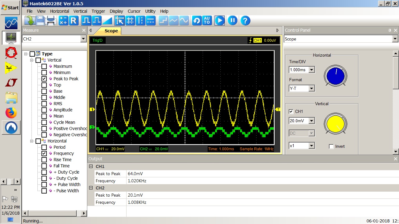
I put a 1Khz signal on it and at 25 - 30 mv it is clipping the signal. I turned it up a little so you can see it clearly. So my take on it is the center stage is so starved for voltage it over drives with a small signal. This clipping = detection in an RF circuit. So connect an antenna and over drive to receive a signal. Now what to do?
I changed Q3 emitter resistor to 510 ohm and inserted a 200 ohm in Q2 emitter circuit. The reading were taken after the changes. Notice point 7 went up 1/2 volt. This may allow a little more wiggle room before the signal clips. Let's see what the scope shows.
The green is the input and the yellow is the output. Looks good but I'm just at the point clipping started before.
Back to the antenna test.
This is what I now have with the antenna on the input.
I added a 4 mh choke on the input and I have a little 60Hz but the RF is basically gone.
I like to use connect the dots to do the hook up so First thing I did was number the terminals. (it also helps with referencing the circuit since the components are not numbered)
I made the circuit as presented except I used 2N2222 transistors and 33ufd caps.
I did some voltage checks and recorded them on the drawing. I did not like seeing the center transistor with no emitter resistor. Its base emitter voltage is the first transistors collector voltage. Seems kind of low? So let's look at the circuit with the scope.
I have the scope on the head phone connection with an 16" test lead for the antenna. Yes my local station is 1460Khz.
Maybe I should keep this one on file if I need an RF amp. The 16" leads was picking up so well I put an 8' lead on it.
I put a 1Khz signal on it and at 25 - 30 mv it is clipping the signal. I turned it up a little so you can see it clearly. So my take on it is the center stage is so starved for voltage it over drives with a small signal. This clipping = detection in an RF circuit. So connect an antenna and over drive to receive a signal. Now what to do?
I changed Q3 emitter resistor to 510 ohm and inserted a 200 ohm in Q2 emitter circuit. The reading were taken after the changes. Notice point 7 went up 1/2 volt. This may allow a little more wiggle room before the signal clips. Let's see what the scope shows.
The green is the input and the yellow is the output. Looks good but I'm just at the point clipping started before.
This is what I now have with the antenna on the input.
I added a 4 mh choke on the input and I have a little 60Hz but the RF is basically gone.
Friday, January 5, 2018
Does the DBM output need filtering?
This is not the DBM but it may be representative.
The raw output, unfiltered.
The filtered AF signal.
The raw DBM output. Could a filter help?
Wednesday, January 3, 2018
Monday, January 1, 2018
Oscillator IC data
This is a collection of data about using gates for oscillators. I'm just posting them for reference. The main point is the unbuffered inverter is what TI recommends. If you use more than one inverter (or a buffered inverter) it becomes impossible to control the phase shift as the feedback will 'self adjust'.
TI's App Note specifies unbuffered. Most references on the net seen to leave that part off.
Subscribe to:
Posts (Atom)