Saturday, April 27, 2019

Amp parameters and Z matching - what effects the parameters?


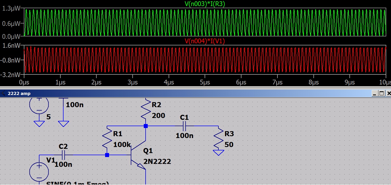
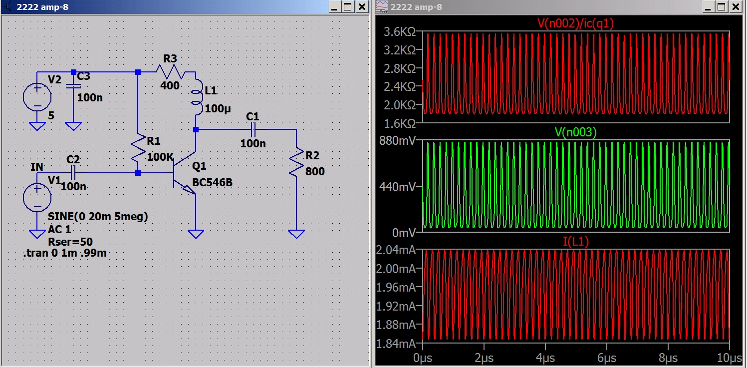
There is a picture story here. I plan to redo it with the node labeled so it is easier to follow.
node 001 is the input.
node 002 is the collector voltage.
node 003 is the output.

Thursday, April 18, 2019

measuring an amps input Z

The question of Z matching comes up now and then. Sadly this is a topic that can become confusing because we have rules that apply to different cases and are sometimes misapplied. If I make a transmitter I want the output Z to be small with respect to the load. The current in a series circuit is the same  thru all components and Power = I squared * R. If we have R1 and R2 (Zgen and Zload) equal they share half the power. If R1 (Zgen) = 0 the load would receive all the power and if R1 (Zgen) = infinity no power can be produced. So for max power transfer we have Zgen = Zload. That is the fly in the ointment. The relationship is developed to show that we ONLY want Zgen = Zload when we are willing to lose half our power. When would that be?
What if I am at work in my 400 megawatt powerhouse and I set the generator equal the distribution system Z? Developing 200 megawatts within the generator would not only be inefficient it would melt the generator in short order. I saw a generator go into 400% overload. It was about 5 seconds and the wire feeding the armature melted and killed power. Something like the fuse link in your car but about a big as my little finger. Ideally I want Zgen = 0 Ohms.
When adjusting the load on a vacuum tube we sometimes see the plates glowing red. Is this good? In this case we need to adjust the load to take more power from the amp. I did a couple of screen shots to show
1. how to measure the Zin for an amp.
2 how the load effect the signal level.
Maybe it will be food for thought?
 First what would we expect to find? We are looking into a forwarded biased junction. The emitter resistance is non linear as is any semiconductor junction. The resistance varies with current so we would need to know the current to determine the resistance. I want to just measure the value and avoid the possible error of guessing or assuming the device parameters.


I put R6 in series with the amp input and measured each side of it to ground. The difference between these two reading is the voltage drop across R6. Finding the current is simple enough I=E/R.
Now R=E*I. We measured E and calculated I so multiply and find the input is 136 Ohms.
This is the junction forward bias resistance and the substrate resistance both of which are not easily determined. Yes it can be done in a different manner but the one just demonstrated is the simplest I know.
Now to test the result.
The generator is set to 50 Ohm.
The generator set to 400 Ohm.
As you can see the generator is dropping signal internally.
Now back to the project of building a RF Amp. My antenna will be a "long wire" with a Z of more than 50 Ohms.
 Time to build the circuit and  RF transformer.

*EDIT: My radio is for 80 meters (4Mhz). The sim show about 6db loss with the higher Z source.

Monday, April 15, 2019

Dummy antenna - other options


This antenna is 100 meters. The curve would be the same for other lengths but the wave length would be different. At 1/4 wave length the antenna is resistive. Below 1/4 wave length it is capacitive. Above 1/4 wave length it is inductive. If your antenna was 30 meters it would be capacitive over the frequency range. So what happens when you connect the generator, go through the alignment and replace the generator with the antenna?

You setup the circuit with a 50Ohm source and then replace it with a capacitor. This de-tunes the circuit. So what can we do?
You could put a short piece of wire on the generator and radiate a signal. Align the set using the antenna it will be using in service. If you are the end user and have the antenna to hook up.
The manufacturer had to develop a way to align the set that would work with their customers antenna. This is what they developed.
The Hallicrafter version.
The Tandy version.

The dummy antenna I posted earlier was the industry standard.

IEC standard Dummy Antenna

If you don't want to build the dummy you could use a small capacitor (100pfd - 200pfd) to couple the signal.

If your set has an antenna trimmer you are in luck. You set the trimmer capacitor to a high value while aligning the receiver. Then when you connect the antenna you turn the trimmer capacitor down to allow for the antenna capacitance.

If you align a set with a loop antenna you can couple the generator to the loop.

*EDIT: Next post I measure Zin and apply a signal with lower and higher Z to see the difference.


Friday, April 12, 2019

Lambda Diode using surface mount devices.

This one would be a lot easier for someone with good young eyes, I'm using a microscope and still having trouble handling  the parts BUT for those brave at heart it could be worth the effort. I'm using a 2SK2539 and a MMBF J175. Lay one on the table right side up and glue the other on top of it up side down. You can see the step, one component is wider than the other.

I flipped them over. The smaller is on bottom and we can't see the step. Notice the writing doesn't show on either side. if it did my parts would not be match properly.
The sources tie together and gate to drain and gate to drain.
Seems easy enough until the soldering begins?


EDIT:
That solder job just about licked me.
If you have leaded JFETs on hand I wouldn't recommend the surface mounts. They do make a smaller package but are a pain to solder. It probably would be better to solder them to a chip of board and use jumpers. It would make a neat package if the JFETs were put in a drop of epoxy.
I just laid the leaded JFETs face to face and made the center connection the positive lead. Check with the ohmmeter and find a low reading to the center pin. (about 40 ohms.) Spare that connection. The remaining connection is the Negative lead. Put it in series with a coil and a 3 volt supply and it sings.

amp in a can with capacitive transformer

You can use different value capacitors. I rounded the values.
 I changed the caps to standard values.

Thursday, April 11, 2019

Converter using LDO - car radio to ham band

If the junk box has a 25XX to 3XXX Khz crystal in it I can cover the 80 meter band. That will be my project. We have an 80 meter emergency ham net in my area. Being able to pick it up on my car radio would be great. Time to visit the junk box.


LDO Xtal oscillator

Measuring at the top of the crystal.
Looks like another rainy day project.
R1 will be a pot so the bias can be adjusted.