Just putting this here before I misplace it.
https://www.clooms.com/50-ohm/
Just putting this here before I misplace it.
https://www.clooms.com/50-ohm/
These scans from the calculator should tell the story.


The old saw is to obtain max power transfer you must match the source and load Z.
The part that is left out is WHEN Zin = Zout half the power is lost in the generator!
Consider the 1000 Mega watt power generator feeding the grid. If it was Z matched HOW WOULD THE GENERATOR SURVIVE 500 Megawatt. The answer is it would not. The wires would melt and the flash over would be exiting. I saw this once. Thankfully the lead is a fusible link. It produced the flash in a confined space.
Anywho, Just look the sims over and see if it make since.

the delay produced by the Tline with matched Z.note the 50% signal loss.


If matching ALL of the circuit only losses half the signal what is the Tline Z?
In other words the Tline is 50 Ohm? So why is there no loss produced when I insert the Tline?
Hint: The Tline is not resistive.
Hint: The Tline is not a flat 50 Ohm. Actually it may vary much more than one might think.
So when they say the Tline is 50 Ohm what does it mean?
Maybe more on this later?
Using an op amp for a simple radio. Single 9 volt supply. An example of how to "split" the supply ans create a reference for the inputs.
https://radio.radiotrician.org/2016/08/op-amp-radio-update.html
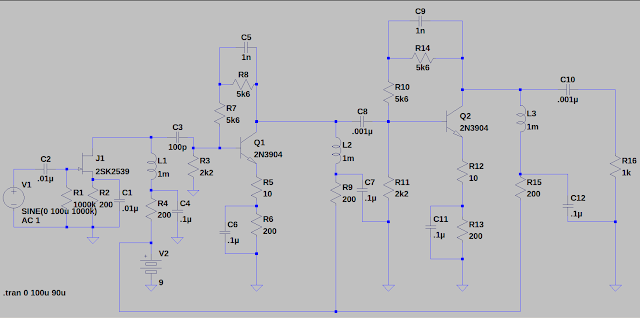
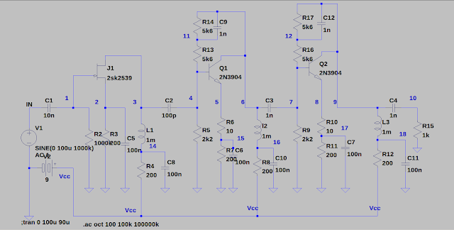
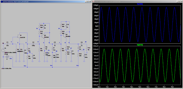
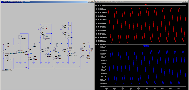
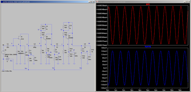
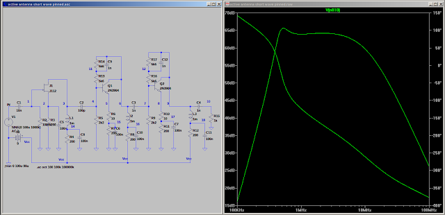 Checkout the frequency response. My target is 3 - 10 meg. Ok for that range? Using a J112 here.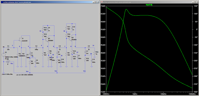
What would happen if we vary R13, R14 and C9?
What would happen if we vary R16, R17 and C12?
Does it need a RF gain pot?
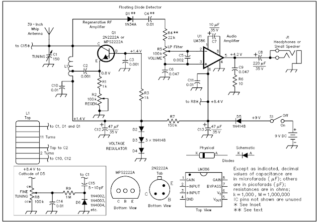
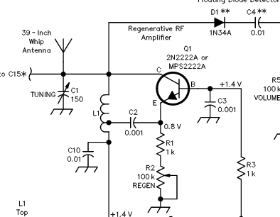
I would substitute a 200 ohm resistor for R1 and use a lower value pot for the regen. My test determined R2 could be around 10K. With the 100k pot it operates close to the pots low limit.
I did assemble the DBM and Lambda Diode set. That is still an option.
I am considering a discrete component Gilbert Cell. While this is a good option it would require a higher supply.
Someday maybe the Gilbert Cell, Lambda Diode, and earbud amp will find their way onto a board. The Lambda Diode does not need a tapped coil so it would be possible to make a socket to use plug in coils. The Gilbert Cell provide conversion gain. This could be the beginning of an all band receiver. It could use one Vcap and plugin coils.
Some food for thought.


