My last board was a real encouragement so I took the next step. Pursuing the goal of layered construction I came up with another scheme. A cross between manhattan and ugly construction.
I'm using a prototype board for the component layout and a double sided board for ground plane and Vcc.
I don't want to cover the base board I just want an island to build on. I cut strips for the assembly.
The manufacturer's Eval board looks like this. My board will provide the same basic function without having to etch it. The large red area is the ground plane. The small red area is AGC. The small strip is the Vcc.
This 3" X 4" board could be used to make 5 amps when laid out as above.
I'll just start with one but I will work close to an end so I have room for another later.
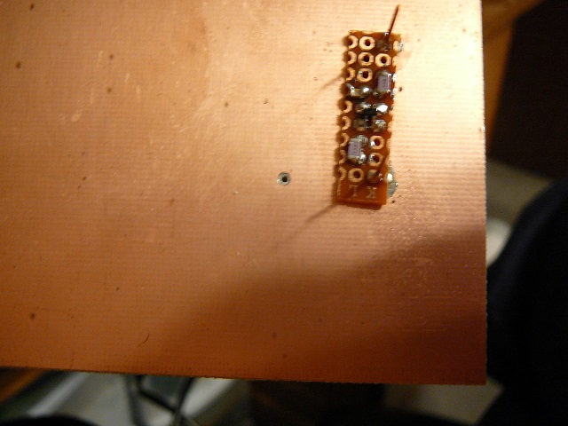
I will need grounds and I need to anchor the strip. I solved both problems by soldering some pins to the ground plane and mounting the board on them. I tinned four pads for the chip to mount on.
Just in case some one is wondering my soldering iron is nothing special. A smaller one might be better but I use what I have.
I mounted the chip and the input and output coupling capacitors.
This is the only "trick" with this method. I need access to Vcc which is the lower foil.I drilled a hole for the wire and then used a bigger bit to remove some foil around the hole so my wire will not short out as it passes through.
I need about 4 volts for AGC so I connect a 10K and 100K resistor in series an solder one end to the ground plane and the other to the Vcc on the bottom foil. The center point will be AGC. ( you could use a 20K and 100K to be closer to 4 Volts.)
Gate 1 connects to Vcc through a 100k resistor so I drilled a hole (as before) and connected it. Connecting gate 2 to AGC completes the biasing.
The source is grounded and the drain goes to Vcc through an inductor. I added a couple of more pins on the top of the board for input and output.
The finished amp ready for testing.
Compared to the one I made yesterday it is more compact. The test will be in how it works. I powered it up and connected my headphone to the output and it just clicked when connected. I put a diode across the phones and I hear the local radio station news broadcast. I tried the first one and found they function about the same.
Now, what could a fellow do with it? maybe a diode ring mixer in the center of the board and use it as a RF amp feeding the mixer. Then another amp connected to the mixer output as an IF amp. Another diode mixer as a detector. Maybe just add a tuned circuit up front and make a TRF receiver.
Gotta be another project in there!


No comments:
Post a Comment