

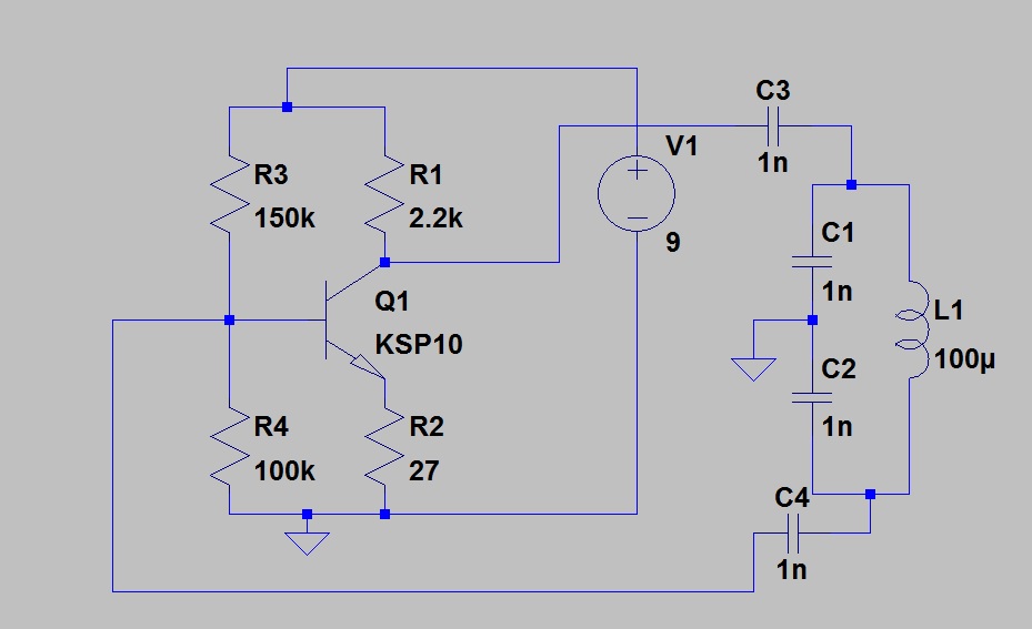

The capacitor divider divides the AC voltage the same as resistors will DC.

You should have no trouble seeing the resistors as a voltage divider (for a DC circuit)

The capacitors provide the same function in an AC circuit. The reactance is set by the frequency. The series circuit has the same frequency so we can use the ratio of capacitance and do the division. Xc = 1 / (2 * pi * f * c) so the larger c has the smaller drop.
Vc1 will be greater than Vc2. With resistors we use a formula such as Vr1 = Ea * (R1 / (R1 + R2)).
With parallel resistors we use:
Rt = 1 / (1/r1 + 1/r2 .......) When we do this we are applying Ohm's law and assuming a voltage of 1 volt.
I=E/R Ir1=1volt/r1 Ir2=1volt/r2 It=Ir1+Ir2 R=E/I
Rt=1volt/It. See it is Ohm's law assuming 1 volt applied.
You can solve the capacitor circuit using the same approach BUT remember capacitor in series add as resistor in parallel so use the conductance to solve it.
No comments:
Post a Comment