Monday, September 23, 2019
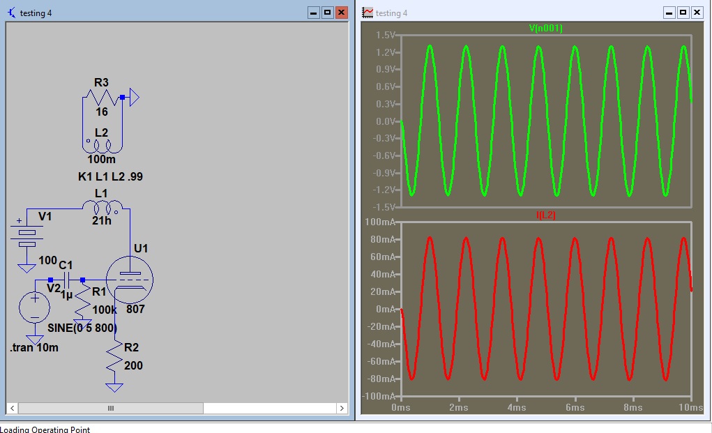
Ear bud or small speaker amp
 |
| 100uv signal will drive the earbud. |
 |
| 1mv signal produces 400ua which is half the ear bubs max rating. |
 | |
| 10 mv is near 4ma drive which is enough to burn out my earbud. |
This amp will require some limiting to keep from damaging my earbud.
What if the output stage used 2 mosfets? I have the 2 -200Ohm resistors limiting the output stage current. I tested the circuit without the 200 Ohm resistors and it produced 20 ma signal. That may be another project.
Saturday, September 21, 2019
The pushpull with a splitter feed
The green is from plate to plate.
The blue and red are the plate currents.
NOTE: These circuits could use some tweaking. I just put them together to see how they functioned. (picking values out of the air.)
Friday, September 20, 2019
Transformer - Z matching - what can we control?
I will make a series of screen shots with the transformer response displaying the circuit response to varying conditions and then pose the question what can we control and what do we have to work around? If we were having a custom made transformer made to our spec's we could just build a circuit and plug in the transformer but that is not the case. I measured a filament transformer inductance and will be using it as a typical example.
If you took the T725 challenge you can calculate the required signals for a 120 volt to 12 volt transformer to match your speaker.
The questions are:
1) What would the valve anode load resistance need to be to match a 10:1 turns ratio with a 16 ohm load?
2) What tube would match?
3) What signal swing would be required for 250mw output?
 |
| This is the reference circuit. The first two readings show the circuit is a reasonable Z match. It is dropping about 1/2 the signal in the plate circuit. |
 |
| decreasing the load decreased the internal signal drop. |
 |
| increasing the load increased the internal drop. |
 |
| Back to the original circuit. Rp is dropping half the signal so the circuit is matched. The only way to increase the output is to increase the signal (100 volts here). |
 |
| If I could lower the generator Z it would increase the output. |
 |
| Lowering the generator more gives more increase. |
 |
| Lowering the turns ratio increased the output. |
 |
The questions are:
1) What would the valve anode load resistance need to be to match a 10:1 turns ratio with a 16 ohm load?
2) What tube would match?
3) What signal swing would be required for 250mw output?
Saturday, September 14, 2019
6 volt 100 mw amp
A low part count 100mw amp to breadboard next rainy day.
EDIT:
I tacked this one on a board tonight. It drives a 2" speaker to room filling volume. I changed R2 to 200 Ohm. I didn't see any 100 Ohm in the drawer and was not going to the shop to get one.
EDIT:
I connected an ear bud to the output and an antenna coil and diode on the input. It plays radio (weakly). It could use a little more signal than I got with my clip lead 'radio'. That would not be hard to do. It draws around 10 ma with no signal at 6 volts.It will work at reduced output with 3 volts.
.
EDIT:
I tacked this one on a board tonight. It drives a 2" speaker to room filling volume. I changed R2 to 200 Ohm. I didn't see any 100 Ohm in the drawer and was not going to the shop to get one.
EDIT:
I connected an ear bud to the output and an antenna coil and diode on the input. It plays radio (weakly). It could use a little more signal than I got with my clip lead 'radio'. That would not be hard to do. It draws around 10 ma with no signal at 6 volts.It will work at reduced output with 3 volts.
.
Friday, September 13, 2019
A trip into water world with a view to electronics
The water pipe analogy has been used for a long time to represent current flow thru a pipe. I want to expand the water analogy a little further. Bare with me.
Have you ever seen this? Do you know what it is? It is a simple and effective way of measuring water flow. It is also a very good analogy of how a semiconductor junction functions.
This is a smaller version of the same device. The principal of operation is based on the relationship of pressure and cross section area of the conduit to flow. Consider the flow thru a 1 square foot conduit and a 2 square foot area with the same pressure producing it. Doubling the cross sectional area would produce twice the flow if all other factors are constant. The device is a flume. The flow is produced as water overflows the gate. the more flow there is the higher the water level will be. You can see the water is higher than the lip and it is free falling as it overflows. In this case the water overflows the flume at a rate determined by the pressure it produces as it rises in the ditch feeding the flume. A self regulating process? Well if it starts raining the flow will pick up because the feed will increase and the level will adjust itself. (self regulating based on the feed rate.
This view shows the operation more clearly. Notice the measuring scales. They are basically bronze rulers that read the water height. The main thing here is overflow. The water flows from a higher level to a lower level.
This is another flow measuring device with a much different operation. It is an underflow.Y1 and Y2 are used to determine the flow. The question is how does this relate to a transistor junction operation? Hopefully the next post will reveal that.
The long tailed amp update
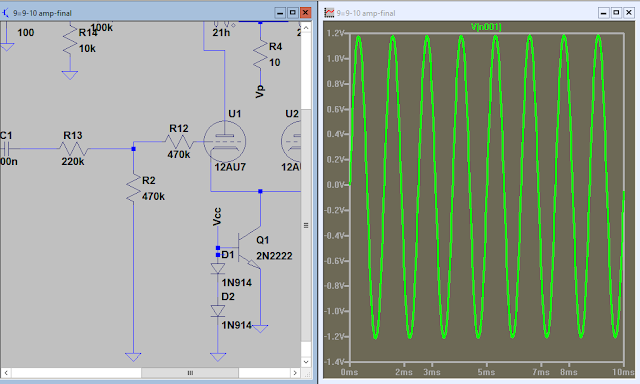
As we begin our adventure into SPICE we needed a circuit to play with. The designer send me one like this.
The quest is to build a long tailed amp. (differential amp? the have several names) Anyhoo, I put this one up for an example. The amp is distorted. The waveform are the grids from left to right.
She saw the distortion being produced by my poor selection of grid resistors.
Increasing these resistor values worked wonders. Adjusting the cathode resistors helped too. She measured .5 volt our with 100mv input after the changes.
So back to the drawing board and this is the final. I also fed the transistor thru a divider because the base feedback was degenerative. The attenuator on the final input helped reduce loading on the preamp.
Wednesday, September 11, 2019
The challege - B725 tap values.
We start with this diagram.
P=I^2*R so what current produces 4 watts power in an 8 ohm load?
if all is well you should be able to determine the Z and turns ratio for each tap. Then double check your work using the ratios given above.
(Z=N^2*8)
The transformer turns ratio and frequency in a commercial product
The transformer could be used as a mixer in the RF frequency range. I'm feeding 120 volts through the 600 ohm resistor and measuring the primary and secondary. The voltage drop across the 600 ohm resistor only leaves a millvolt signal on the transformer.
With 1 volt input the signal is dead.
with 100KHz input the primary receives 1 volt. The reactance is well above the 600 ohms in series.
We normally use 600 ohms in audio systems and 50 ohms in RF so I changed the generator to 50 ohms.
I changed the time base to show the signal is sine wave, no distortion. Take note of the turns ratio and inductance ratio.
Monday, September 9, 2019
Another amp to look at in spice. With different transformers.
Subscribe to:
Comments (Atom)


