Tuesday, February 22, 2022

simulators can be fun but...

I have been using EZNEC in WINE on a linux box.

 https://www.eznec.com/

It works quite well but the screen size is to small for my ancient eyes.


I did a screen shot and enlarged it. The red note says the wire segment is to long. Note wire 2 Y = 70 feet.


I shortened the wire to 60 feet and the red went away. Looking back at the first comment it says segment to long? Now look at the last column. 2 segments. I changed it to four and set the wire back to 120 feet. All is well. It would help to know some function running the math? Apparently the wire is divided into segments as part of the calculations?

Anywho here is the screen shot from Xnec2c ( the linux version of NEC).


I learned something if I can remember it. Get the magnifier and read the comments carefully.

Thanks to Andy for the references to 

nanovna-saver andSimNEC.

I downloaded and install both. They work well under Ubuntu.

I connected the nanovna to a 2 meter wire clipped to an ac register and the programs connected to the vna and displayed the antenna response.

They are fun to play with but will have some learning curve.

A sample shot from  simNEC. 


It plots the response and you build the network by simply click and drag.


Z matching is not all to be concerned with

 How would you connect a dipole (balanced system) to an unbalanced receiver? Problem is the dipole is not grounded and the receiver terminal is.

The balun not only overcomes the grounding half the signal problem it also add common mode rejection. As that antenna lead travels down from the attic it is subject to various noises. Terminal 1 and 2 feed the signal out of phase and the transformer passes it to the secondary. Noise arrives in phase and the center tap of the transformer disposes of them without any going to the secondary.


Monday, February 21, 2022

Z matching continued...


Motorola app note

Motorola AN-0721 Z matching RF amps. The place to start

 volume one

Volume one of two. 526 pages of data to start the journey.

 Volume two

Volume two of two. 576 pages of data to continue the journey.


Wednesday, February 16, 2022

Z matching part 2

If you read the first part of the tutorial I linked in my last post this may be your uh hah moment. I will post one sim that tells a lot about web wisdom and reality. It will also lead to more questions. I hope to do another post to continue the story of Z matching. The journey continues.


In the simulator you can set the generator Z and it will not be displayed. For this sim I set the internal Z to zero and placed a 50 ohm resistor in series with the load. Remember Power is equal to current squared time resistance. In both cases I have the same load so the power increase or loss is a square function. I(r5) is more than twice I(r2) so the power delivered is more than four times as much. Look at the voltage delivered to the loads. V1_out is one half the generator voltage wish tells Zg = Zl. Web wisdom  states max power transfer is when Zg = Zl but they do not finish the story. The tutorial begins with that as the first step on the journey. The second step is to understand the power loss internal to the generator is one half of the available which is not acceptable. 

1st step = Max power transfer Zg = Zl

2nd step = The generator is going to at least waste a lot of power and possibly smoke

3rd In some cases the power transfer is more efficient when a PROPER Z mismatch is used.

Years ago we were taught to use a MINIMUM of a ten to one ratio.

Later they said we should use a MINIMUM of 100 to one.

When do we really need be concerned about matching and how do we apply the matching for best advantage? 

To be continued ..........


Tuesday, February 15, 2022

definitive tutorial on Z matching ( 70 years ago )

When I took this course in 1960's it was state of the art. It is a little different today but the basics will never change. That said if you study this little 40 page tutorial you will have the basics for Z matching far beyond the one line continually misapplied. Many an expert will tell you that one line and stop. It is not meant to be the definitive statement but rather the teaser line that draws you into the study so either ignore the post or be prepared to study at least the first 5 or 6 pages. If you read the first page and say "that is what the other guy said." you will miss the point. It is the lead in not the final statement. So for the brave download and read the document.

Z Matching


Antenna data


Sunday, February 13, 2022

Antenna tuner data

 Just putting this here so I don't misplace it. It matches a low Z transmitter to a high Z load.

When feeding a high Z (100k's - meg ohm)receiver input circuit from an antenna with relatively low Z (less than 5K expected) could we benefit from this matching. Matching in order to produce loading in a transmitter and matching to produce maximum signal transfer in the receiver. 


Wednesday, February 9, 2022

Antenna matching in sim

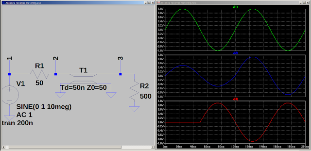
 In this series of shots I have the generator representing the antenna (signal). The Tline represents the coaxial cable. The load resistor represents the receiver. If you examine the series you will see matching for maximum signal to the receiver does not mean making the impedance's  equal. 

Two things to observe.

1. A minimum of a 10 to 1 Z ratio is better than Zi=Zo.

2. Reactance is our enemy. With resistors things go smoothly. Adding reactance upsets the apple cart.


In the last shot it could be said I did a conjugate match.

It may also be said I neutralized the reactance to make a purely resistive circuit.

In the antenna circuit power may be measured in nano watts and voltages in micro volts. With a low (less than 400) ohm source and a load of several KOhms the voltage is what counts. A reactive source reduces the voltage. 

Food for thought.


Tuesday, February 1, 2022

inverted VEE antenna

 Was looking at Cap top hat and came across this.

 Storing it here.


Inverted Vee