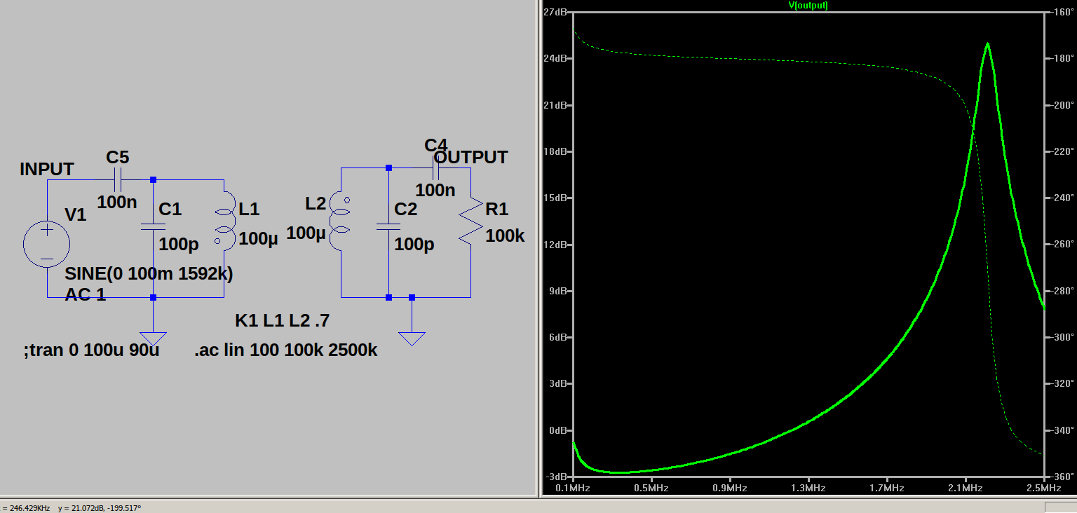
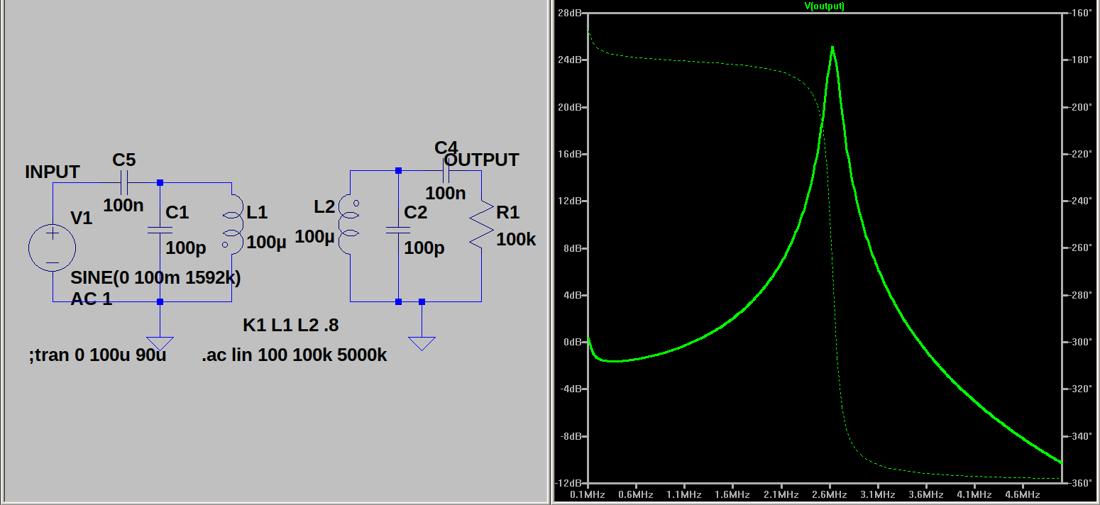
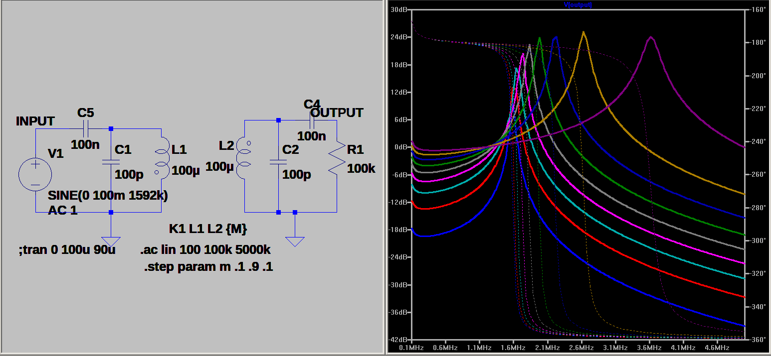
If you examined the previous post you should have observed over coupling reduces output in an IF transformer.
If you examined the previous post you should have observed over coupling reduces output in an IF transformer.
As you scan the sims observe K, OUTPUT currents. You should observe at K=0 there is no coupling. At low values of K the output picks up quickly. At high values of K the signal drops off again. You can not see the whole picture here. In the next series of sims I will show that changing K also changes the coils inductance. Loading the coil shift it inductance.
The output is half as much at K=.5 as it is at K=.25. Why is this?


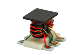
They used color coded wire which could help avoid confusion. Winding 1 coil at a time helps prevent confusion too. You need 2 of these to make a DBM.
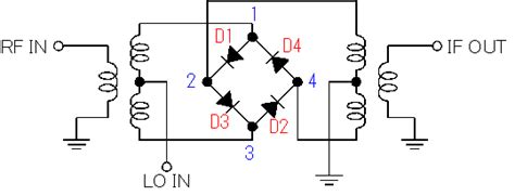
2 transformers, four diodes and a local oscillator will make a receiver. The IF will be audio in a direct conversion receiver. 2 mixers and an IF section will produce a double conversion set. Fun to play with and easy to make.
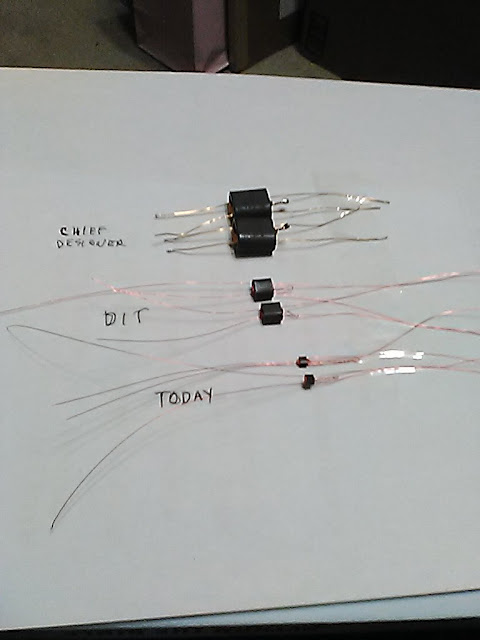
The top one is wound on the type core The Chief designer and I used in the original 40/80 receiver. He wound it himself!
The middle one was the next one in the progression. Designer In Training wound it for him. He bragged she had excellent vision. Good hand eye coordination too!
The bottom one I wound today. I used an eye piece and stumbled through it. For reference the wire is #34.
Two a day is about all I want to wind. Anywho time to build some DBM's. Our previous test told us the smaller ones performed better. The new one should be spectacular????


This was my original circuit. A quick look at the scans will show I changed the value of C3, bypassed the output with C4 and added a choke. This change removed a lost of noise in the output.
We hear about the Q sometimes as though it is impossible to comprehend. I will attempt to help clear some of the allusion. The Q is simple a ratio of resistance and reactance. First a sim , then a test.

I made these coils and they were just laying on the bench so I will use one of them for the test.

The jig is quite simple except the circuit load the generator and the test is invalid. I tried using a 1K resistor to eliminate the loading. It sort of worked. It takes 10 volts in to produce 1mv across the test circuit.

without the resistor I get about the same input with 1 volt.

Using a transformer the results are much better.


I learned a couple of thing from this test.
1. The test signal should be less than 1 MHz. What range is your meter good for? My meters are rated 100KHz so I would look at using maybe 50KHz to 100KHz.
2. I show 2 caps in the circuit. One is adjustable and one is fixed. You can use the fixed to get close and then tune the circuit with the adjustable.
3. the RF transformer needs to be in range too. Watch the core rating.
NOW!
What about that Q. Examine the test circuit and you will find the input is in parallel with a coil and cap in series. The first meter monitors the resistor voltage. The coil and cap will have Er times Q volts across them. The voltage on the coil and the cap are 180 degrees out of phase. In a resonant circuit the coil charges the cap and the cap charge the coil. It is like a juggler passing his balls from one hand to the other. Look at the charge and discharge path for the series resonant circuit and you see the input signal is in series with it. So we have Es in series with and equal to (El - Ec). And this is Q in a nut shell. El can be equal to Es or it could be 100 times Es. What determines this value?
Circuit resistance does. If the coil reactance and resistance have a ratio of 100 the Q is 100 and the voltage gain is 100. How can this be? Remember the circuit has +jx and -jx values which are equal and therefore cancel. The current limiting factor in the circuit is resistance. Remember E=I*R. In a series circuit I is the same throughout.
E reactive is amplified by the coil based on the current limit the resistance establishes.
That's it.
The coil field builds and store energy limited by the resistance. (In theory it will take all the power source can supply.)
The coil field collapses and attempts to maintain the current limited by that same resistance. (Of course in practice we see losses but this where the elusive Q comes in.)
A purely reactive circuit would have a Q of infinity.
A circuit with the resistance equal to the reactance would have a Q of 1.
And so the journey to finding Q begins.

Before we can examine a detector we must define the type - high level or low level? The diode has 3 sections in its characteristic curve. It can be cut-off, conducting or in the twilight zone called the square law region.


In a high level detector the diode is switched on and off. Then the RF is filtered to develop the audio. We would see this type detector in a tube or transistor radio with the signal amplified before being detected.
The following screen shots show the small and large signal detectors.


Now the Z match in one page.

Notice when the Zin matches Zout half the power is lost in the generator. In a crystal set working in the micro volt range this would be a problem. See the alternate definition of Z matching on the right hand column.

Look at the load on the printouts. This chart relates a 100 Ohm source to loads from 1 Ohm to 10000 Ohms. The 10k load receives a higher %age of the power. This would be good for the small signal detector. The higher the better?
Look back at the large signal detector. It could drive a high Z head phone?
So the first step is define the project and stick with the design. Don't talk apples and oranges.
A crystal set is limited by the signal and power levels. A TRF or superhet would be a different animal.
While you are thinking about these things consider the antenna system and feeder system. A transmitter hookup would require a large signal approach. A receiver could be more small signal approach.
