Wednesday, February 9, 2022

Antenna matching in sim

 In this series of shots I have the generator representing the antenna (signal). The Tline represents the coaxial cable. The load resistor represents the receiver. If you examine the series you will see matching for maximum signal to the receiver does not mean making the impedance's  equal. 

Two things to observe.

1. A minimum of a 10 to 1 Z ratio is better than Zi=Zo.

2. Reactance is our enemy. With resistors things go smoothly. Adding reactance upsets the apple cart.


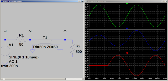


In the last shot it could be said I did a conjugate match.

It may also be said I neutralized the reactance to make a purely resistive circuit.

In the antenna circuit power may be measured in nano watts and voltages in micro volts. With a low (less than 400) ohm source and a load of several KOhms the voltage is what counts. A reactive source reduces the voltage. 

Food for thought.


Tuesday, February 1, 2022

inverted VEE antenna

 Was looking at Cap top hat and came across this.

 Storing it here.


Inverted Vee


Monday, January 31, 2022

Proof of concept.


Yes. When I allowed for strays everything fell in place.


It is in how you figure?

 If I have a 200uh coil and I want to tune 1-5 MHz what value should the tuning cap be?

1MHz     2MHz    3MHz    4MHz     5Mhz

126pfd    31pfd     14pfd    8pfd       5pfd


Now if I mark my dial the scale does not match my Vcap values. Why?


Notice the only place it is close is with the hi value cap. The lower the cap the more the strays effect the circuit.


When the dial does not match we can measure the cap and calculate the inductor value.


1MHz     2MHz     3MHz     4Mhz     5MHz

129pfd    34pfd     17pfd      11pfd     8pfd

196uh     186uh     165uh     144uh    127uh

If we do not account for the strays it appears the inductor is changing value.

Maybe another series of scans with the adjusted values is in order?

Friday, January 7, 2022

RC transmitter in sim


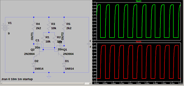
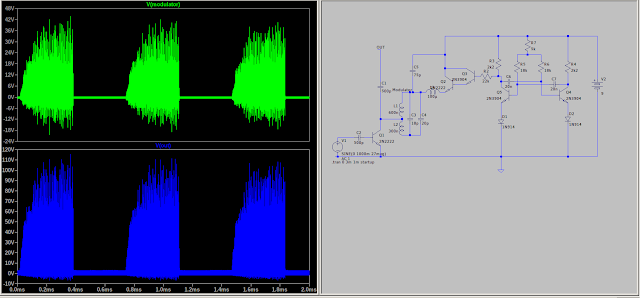
 The multivibrator chops the RF signal by switching the darlington pair on/off. The Darlington supplies power to the oscillator.


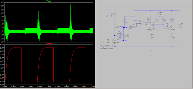
The antenna is open circuit and the standing waves are there but you can see the switching.


Placing a resistor for the antenna produces a cleaner out put.

I have no data on the antenna. Something else to investigate?


RC transmitter from Radio Constructor mag Sinclaire ST140 ST141

 I am just putting this here before I lose it. I am locked from TRB again. A new member asked about Sinclair transistors.


It works in the simulator using 2N2222 and 2N3904 transistors and 1N914 diodes.


Thursday, January 6, 2022

Using a DBM as a modulator for my KKMOON generator.

 Silly me bought a KKMOON Dual Channel Generator. Nice little generator but it has to be programed. When I used Windows XP I could attach to it and produce a modulated signal. It was a pain programming, instructions not in English. Anywho I no longer have the program and I really want to be able to modulate the signal. My solution may not be the best but it was easy to build and works.

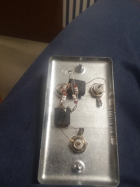
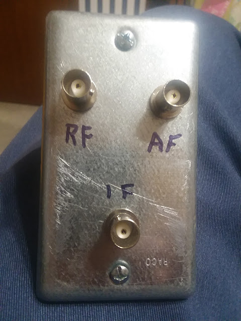
The DBM is simple to build just 3 connectors, 4 diodes and 2 transformers.


It is made on a handy box lid. The 2" X 4" electrical box makes a good rugged project box.

I tried it and it worked well. 

I will make some "custom" cables.