Saturday, February 20, 2016

Mutual inductance effect on transformer action and impedance matching

For this test I wound a transformer matching the one I posted about earlier. It has 3500T : 500T. I expect it to perform similiar to this one.
 

For a comparison I wound one with 1000T : 100T.  Then I bread boarded this test jig.

The one thing to remember is that the tail cannot wag the dog!  No matter what the Z load  is the Z input will only go as high as the inductance of the coil at the operating frequency so I establish the base line (start point) but checking the primary with no load. The 3500 : 500 read off the scale so I established the start point fo it at 19H with 490Ohm load. here are the results of the test.

1000 : 100
open circuit          4141mh
5KOhm               4123mh
50Ohm                2146mh
25Ohm                773mh
10Ohm                4.3mh


3500 : 500
490Ohm             19H
372Ohm              15H
261Ohm              10H
153Ohm              5H
45Ohm                1H
0Ohm                  .21H

The math says this is a 36 Henry primary. since my meter only goes to 20 Henry I loaded it to get 19 Henry with 490 Ohms. So the input impedance would be more than 48K for a load above 490 Ohms. The chart above says 25K : 500 Ohm so what's up with that?

 The plate circuit is a voltage divider. The plate resistance in series with the primary will divide the voltage as the current swings. As plate resistance goes down and plate current go up the primary develops a voltage which oposes the change in current and induces an output in the secondary.

Friday, February 19, 2016

How fuzzy is the twang-a-matic?

I decided to see just how fuzzy the twang-a-matic is and here's the result.


The yellow trace is the input and the green is FUZZY!
I made this one with GE transistors I had on hand . I'll have to do it again with some GS109s when I get them. I have two great nephews who are in a band I guess they'll need a couple:).


Coil design and construction for the hobbiest.


Babani coil construction

First I would strongly recommend this book. It doesn't go into a lot of high math just tables and charts and a few places where you multiply or divide to find your value. You find a value on a chart and then use ratios to obtain your coil of choice.It's less than 100 pages but tells you all you need to know to make your inductors.


There is a lot of discussion about impedance matching and trying to determine whether a certain transformer will work or not. I'm just going to throw out two or three things to consider and the recommend the book for more detail. First a simple example to demonstrate one of the problems encountered in transformer selection.

If you take a filament transformer and apply power to the primary through a light bulb with the secondary open the lamp will not light. Short the secondary and the lamp will light. Why? The primary current is being opposed by the inductance of the core material. The field expanding and contracting magnetizing the core produces counter EMF which limits current flow. When the secondary is loaded the current in the secondary is also 180 degrees out of phase with the primary AND it produces a counter EMF which cancels part of the primary field allowing more primary current to flow. This primary field cancellation by the secondary allowing the primary to draw more current is being limited by the lamp in the illustration. If you did the same thing without the lamp you would burn the transformer out.

In the case of a plate load transformer the tubes ability to supply power to the primary will determine the ability of the transformer to supply the load. Here is the thing about the plate load in a nut shell. The primary needs a voltage dropped across it in order to produce a voltage on the secondary. You can put any transformer you have in the plate circuit and get something on the secondary. What you get will be determined by the primary Z and the turns ratio. In the case of an inter stage transformer we want a high inductance in order to develop the voltage and we would like a step up transformer for GAIN.  If you look at the magazines from the early years you will see transformer coupling was almost universal. In those day the tubes were very expensive an transformers gave a cost saving. Yes without the transformer the amp would need a third stage.

So the quick rehash. The primary Z determines the transformers ability to develop the signal and the turns ratio determines the Z matching. In the case of an inter stage transformer it is matching a low plate Z to a high grid Z and we can obtain gain from the turns ratio. The following are from the book linked above.

Notice the higher secondary turns ratio allows the primary to be lower. Remember the light bulb? The higher Z  load on the secondary produced more output voltage with less load on the primary. This transformer is feeding the grid of the next stage which could be a megohm.
 The charts show the effect of the different turns ratios. Is it what you would expect?


If the inductor is placed in the plate circuit it will carry DC and that will magnetize the core which will lower the inductance. This will require a lossy core to prevent saturation, Thus the air gap. Amp turns is exactly what it says the number of turns times the amperage. Example #1 5 MA times 6300 turns gives 31.5 amp turns. look at the chart and see this will require .001" gap. As the core is assembled a piece of fish paper or wax paper or tape or some non magnetic material would be placed between the E and I laminates to allow for the DC.

If this doesn't answer the question. Read the book.


Wednesday, February 17, 2016

The worlds simplest oscillator.


I was thinking I could use an audio oscillator and found some 3N58 SCS's in the bin. Relaxation oscillator are the simplest to build and can be interesting. These 3N58 or 3N83 SCS circuits may be worth a little time to study. as the diagram shows they consist of two transistor in one case with all their elements available at the pins. These were the start to a new line of components which are used every day around the world. As you can see from the schematic they have a cathode/gate and an anode/gate. This one device is actually three in one. It can be used as a PUT or SCR. first the SCR.

 
While the SCS has four leads the SCR has only three. The NPN transistor collector and PNP base junction is not available at the pinout. now a look at the PUT.
 
With the PUT the NPN transistor base and the PNP collector junction are not avalable at the pins.
 Now let's look at some oscillator circuits using these devices.


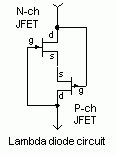
 All these are fairly simple and straight forward but they need a SCS, SCR or PUT. what can we do without these special purpose devices? How about a lamda diode?
 
Probable the simplest Lamda diode is this one. Still we need a P-ch and N-ch JFET. You can build this with junction transistors but that requires biasing. While that's an interseting study it isn't going to produce the simplest circuit. Back in the day you would just put a neon lamp across a capacitor and charge the circuit with a big enough resistor that once the neon flashed and discharged the capacitor it would limit current below what the lamp needed to stay lit. This brings us to the negistor. Actually the circuit below is not the simplest but a tone control and switch are good things.


Another interesting device which will have to be left for later is the zinc oxide negative resistance diode. It's a quick google search to find one but be warned it can pull down the dark hole of experimenting!
I guess the simplest oscillator is the negistor oscillator. One last thing. Yes the negistor can be crystal controlled.

Updated Lambda 

 second most simple oscillator

ZN414 Radio


A TA7642 IC IS BASICALLY THE SAME DEVICE. EASIER TO FIND THESE DAYS.

Tuesday, February 16, 2016

What is the effect of DC on coil inductance?


If Xl = R  the inductance can be calculated. Doing this without DC will give the inductance of the coil to AC. Set the DC current you expect your circuit to pass throw the coil and check again. If Xl is decreased drastically with DC your inductor may need an air gap to 'lose' some lines of force and prevent saturation.Inductive coupling is through the coupling of magnetic lines. The core's purpose in to contain or concentrate the lines. As the field builds it will reach a point that no more lines can be contained. At that point magnetic coupling ceases.

4 microwatts driving a headset?

 
 In the article he calculates the headphone power to be 4 microwatts. The silver cell produces 0.7 Volts unloaded and drops to about 0.5 volts under load. The phones are 110 DBM. They produce 110 DB sound pressure at 1 milliwatt. Need a math wiz here 1 microwatt is 1/1000 of a milliwatt so..........

The question I had was how much signal it would take to drive a headphone or earbud.  The headphone is 110 DBM and the earbud is 90 DBM. From what he says I thinking just a few microwatts.