I will try again to show the transistor action. Whether you want to see it as a voltage controlled current source or a voltage controlled resistor the test should help with that.
Keep in mind semiconductors are non linear and Ohms Law is still in effect. E=I*R and we can not change one parameter without effecting the others. First how can we transfer resistance in the device? Apply a forward bias voltage to the base - emitter junction and the base - collector junction resistance will change. The main parameter is ß (beta). Beta is the ratio of current in the base and the collector. This too is non linear so we must read Beta at our operating point for it to be accurate. First let's look at the beta of a transistor at three points.
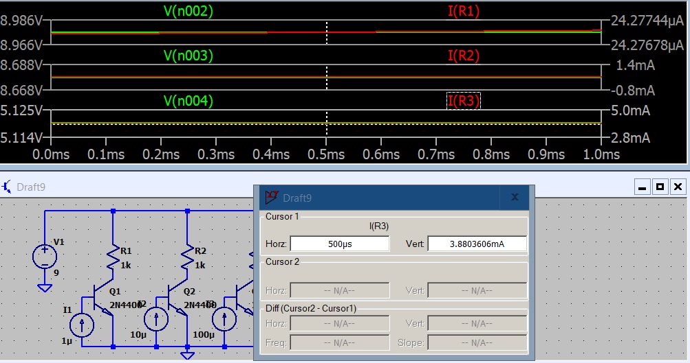
 The three stages have 1uA , 10uA and 100uA base current.
Q1 has 21uA so beta is 21/1 = 21.
Q2 has 320uA so beta is 320/10 =32.
Q3 has 3.9mA so beta is 3900/100 = 39.
Notice a 100 fold change in base current almost doubles beta.
Let's see what happens when we produce a 10 fold increase in collector load resistor.

Looks much the same. Let's increase the collector resistors again.
 I added the collector voltage so you can see the circuit will current limit when the load resistor drops the supply voltage.
 Raising Vcc to 9 volts raises the collector voltage. The current through the load resistor is the same as before so the drop across it is the same. The 'excess' Vcc is on the collector.
The next 3 screen shots show even with Rc increasing from 50 Ohms to 1K and Vcc going from 5 volts to 9 volts the collector current is the same.


 This should make it clear a change in base current will produce a change in collector current. If the supply voltage and collector load are within the circuit limits that current will be reasonable close to the same for a given base current and device beta.
The next step would be to explore how to set the base current. Actually I did that here: Fixed Base Biasing
The fixed base biasing is ok for small signal hobby circuit but is prone to thermal runaway. The next step would to look at methods to stabilize the circuit.
Keep in mind semiconductors are non linear and Ohms Law is still in effect. E=I*R and we can not change one parameter without effecting the others. First how can we transfer resistance in the device? Apply a forward bias voltage to the base - emitter junction and the base - collector junction resistance will change. The main parameter is ß (beta). Beta is the ratio of current in the base and the collector. This too is non linear so we must read Beta at our operating point for it to be accurate. First let's look at the beta of a transistor at three points.

Q1 has 21uA so beta is 21/1 = 21.
Q2 has 320uA so beta is 320/10 =32.
Q3 has 3.9mA so beta is 3900/100 = 39.
Notice a 100 fold change in base current almost doubles beta.
Let's see what happens when we produce a 10 fold increase in collector load resistor.

Looks much the same. Let's increase the collector resistors again.


The next 3 screen shots show even with Rc increasing from 50 Ohms to 1K and Vcc going from 5 volts to 9 volts the collector current is the same.


The next step would be to explore how to set the base current. Actually I did that here: Fixed Base Biasing
The fixed base biasing is ok for small signal hobby circuit but is prone to thermal runaway. The next step would to look at methods to stabilize the circuit.