Friday, March 30, 2018

Aluminum brackets to mount volume pot with from old door frame

 The bottom feeder in me would not let me throw away these storm door frames. What good are they? I needed some brackets to mount some pots on.


Look at that big old "L" bracket! Remove an ear from each side and set that bracket free.
From this angle you can see one ear sticking up and one sticking down.
I'm using a router free hand (except the bit has a bearing). One pass and one ear gone.
A little closer look. See the ear is gone.
I flipped it over and made a second pass. With the two ears gone I have my "L" bracket.
I cut off the piece I am ready to use.
Just another view.
A quick trip to the chop saw an I have my four brackets.
As you can see here they have a little bow in them. I could put them on the anvil and give a couple taps with a hammer to straighten them.
A closer look.

Monday, March 26, 2018

2SK2539 modeling

I made a little adjustment to the spice model.
This was my first try. The insert is a cut and paste from the datasheet.
Getting better?
That's more like it. I may do better when I have some time. I think it is close enough to use now. I will build a circuit or two with it and see. I made the earbud amp from the previous post and it works well.

Sunday, March 25, 2018

Earbud Amp in sim and on board

I am just going to post the data and let the reader decide but a little intro. The JFET can be used as a constant current source. If you connect the gate and source and apply a voltage it will self regulate at some current. When you look at the datasheet this value is given as Idss. The JFETs I'll be using ar 2Sk2539s. Arrow.com has them on sale for $0.005 each which is $15 for a reel of 3000. With free shipping that was hard to pass up. So I will be using the 2Sk2539s for all my circuits for some time to come. They are high frequency amps so it will be possible to build a set with them exclusively. Now I'm passed the intro, here is the Idss from the datasheet.

Observe Idss 10.0*      50.0*.  See the note. They come in AK(6,7,8) 3 different ranges of Idss. The 10 - 50 being broken into three pieces. Mine are AK7 which is 16 - 32 ma. It is good to know I can pass that much current without damaging my JFETs but I like to not drain my batteries any more than necessary. My goal will be less than 1 ma for each stage. The JFET can be looked at as a voltage controlled current source. It has a self regulated current when the gate is tied to the source and when the gate is biased with a set voltage it will regulate at a different current. So the problem is to determine at what voltage to set the gate. Fortunately the device will find a point of operation on its own if we just provide the bias and we can provide a negative feedback by simply placing a resistor in the source circuit with the gate tied to the other end. The Vgs(off) or pinch off voltage is also on the sheet above. -0.6 to -3.0 volts with -1.4 volt typical. So I GUESS I can place a 2.2k resistor in the source circuit and get a drain current well below 1 ma. Now to the sim.
So I 'throw' together a circuit with 2.2k resistor in the source and drain. My earbud will be 64 ohm and I placed one in the source and drain to see where it might be best placed. Some like to put them in the DC path I think any DC in the earbud is not good. They are to easy to over drive. Anyway you can see the one fed through the capacitor rides a zero bias and the other is riding a 350ua bias. Other than that they are much the same.
Here I placed a capacitor in both circuits and they are identical except for being out of phase.
If you have a 2k headphone you can use this circuit. Here again make no difference if it is fed from the source or drain. Why is this? We have the same current flowing through the resistor s and they are the same value. What would happen if we raise the drain resistor value?
How about the other drain resistors???


It will drive an earbud and headphone. Will need a volume control.
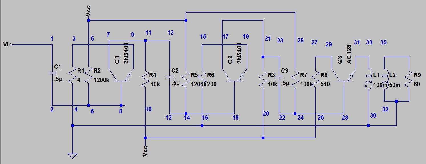
The as built circuit for my earbud. 1uv input 800uv output. I did put a 100 ufd capacitor across the supply terminals. This helped stabilize the supply to prevent feedback on the supply line.
You may have noticed I used 2SK117s in the sim. I don't have a SPICE model for the 2SK2539. My next project will be to build a model that more closely matches my circuit.
To be continued..............

Thursday, March 22, 2018

FUNNY?

My friend sent this. I wonder if he is trying to tell me something?


Anyway I found the problem with my soldering gun. I'm going to fix it so I can go back to work on my project.

Just a couple of drops of solder and a little tape and it'll be good as new!


Wednesday, March 21, 2018

2N5401 amp part 2


I did not show the simulation before so I will now. With 100uv input I get 110mv output. This is way to much my ear phone only needs 1mv or 2mv to sing.

The last post I had mounted the components but made no interconnection. Here I added the interconnections and am ready for a test.
The low range on my scope is 20mv but it has a voltage readout so I use it. 2mv in and 1.2volt out is good. My AF generator is on minimum and it is over driving. I may have to put a little negative feedback on it to lower the output. I am going to try it as is before doing any modification.
I made some I/O ports on a 2" X 4" box cover.With a switch, volume control, input jack and output jack It should be good to go. The question will be shall I mount it in a box? Anyway the next step will be wiring the I/O, switch and pot.

EDIT: I put a bypass capacitor across the battery. The set was a little unstable with my bench power supply. It was better with a battery. The capacitor settled it down with the bench supply. It could be the supply reacting to load? It is voltage and current protected?

When I get back to work on the 40/80 this may be my AF amp. I put a small telephone receiver (145 ohm speaker) on it and it was load enough for easy chair listening.
EDIT: This amp will work with a single rechargeable cell. (1.2Volts)

Ferrite Antenna data and an example of its use

Ferrite Antenna Data

This article tells the story quite well. A real world example is the DX-160 receiver.
 The Dx-160 is an all band shortwave receiver. It has 5 bands. You can see 5 coils in a row. The alignment process calls for setting The coils at different points on the band. The final step is setting the ferrite antenna coil for each band.
The ferrite rod has a coil for each band. If you read the linked article you will understand the position of the coils effects its inductance. They are wound to be set off center when adjusted correctly.
Here is close up of the coils.


The ferrite antenna on the schematic. (T1 - T5)
The Dx-160 using the ferrite rod antenna
The ferrite rod antenna from the article that I am responding to, it is a tuned circuit being fed by the ferrite. The ferrite is 87uh and the tank coil is 2uh. Coils in parallel that are not magnetically coupled at as resistors do. 87uh in parallel with 2uh = 1.995uh or for practical purposes 2uh. At the other extreme 87uh in parallel with 12uh = 10.7uh. As long as the coils do not magnetically couple you can treat the antenna as a signal source and not a part of the tank. The small amount of interaction would be adjusted out when you tune the circuit. For best results a 10 : 1 ratio or more should be used. The 87:12 ratio is a little to low.

That article also referred to a Small Magnetic Loop.
Here is an example of the small magnetic loop.

Here is the magnetic loop with an amplifier from the same article.No ferrite used here. If this one had a coil on the fet gate and it was equal the loop inductance it would be what the article refers to.

Monday, March 19, 2018

RF Probe for DVM

So many projects and the list is growing. How can you do RF work without a scope? Maybe a good RF meter would be a reasonable substitute. Even my cheap DVM has a 200mv DC scale. With a RF detector built into a probe this becomes a sensitive RF meter. If you rectify an AC signal and send the signal to a DC meter you read peak. RMS is .707 peak so the 200mv DC is about 140mv RMS. For signal tracing and checking to see if a circuit is oscillating you just need a relative reading. So the last project added to the list is one of these.
Or one of these.

As always the project is open to modification. Either of these two would be a good start. Ummm? I had a TV antenna come apart when the tree hit it in one of the hurricanes. I saved that aluminum tubing for just such an occasion as this.
A little tubing, a finishing nail filed to a point, a diode, capacitor and resistor. Need two to check an amp input and output. Using the same meter and probe will give a relative reading that could be used to determine gain. You could use a signal generator and 'calibrate' the meter against it.


2N5401 Amp part 1

The method is fairly simple. Place all the components on a board and connect the dots.
This is the circuit as 'built' in LT Spice.
I relocated the parts in a line and kept the wiring the same.
I just drew some lines on the board to aid the layout.

I numbered the lines as I had labeled the drawing.
I like sequence pins because they are short and sharp. Easy to press into the board and short enough they don't go through.
I wrote the part numbers between the pins. Even I should be able to read the number , look at the parts list and connect the part between the pins.
I located all the parts and put them in my handy parts holder (soap dish). That's all there is except a transformer, phone jack and volume control.
Now I have all the parts installed except the transistors. I will install them last. tinning  the pins so they require a minimum of heat.

Sunday, March 18, 2018

The project I wound the transformer for


I plan to make these two just for the fun of it. I made the bottom one using off the shelf transformers and sockets so I could try different transistors. It worked. I made 3 transformers so I could use one for the output.

Winding some transformers for the AF amp

I upgraded my coil winding machine. It was like this. It did work but could use a counter.
They have these for $35 - $40 on E-bay so I bought one.
It is really nice to have a counter. I can stop and come back and not lose count. I did have a problem with the shaft. It is about 3/8" so I was limited in the size coil I could wind. I decided to add a chuck and make it universal as the original was.
It was not quite as easy as I hoped but it wasn't to hard. The gear on the drive end is pinned on so it was just a matter of removing the pin and the old shaft would pull out. The other end need threads to screw into the chuck. You can see in the picture the mandrel came with tapered coil holders. They fit in the end of a coil and turn it. So what can be done about that?

The guys in the chemistry lab use these to plug flask. They come in several sizes. I bought a pair in three sizes I thought might be useful and drilled holes in the center for the shaft. I used 1/4" all thread for the mandrel. These worked well with my transformer cores. I used a #8 screw for the mandrel for my pot cores.

With this setup I simply zero the counter and thread the wire. Turn the crank until the counter reaches the desired count. It works well.
I'll have to build that AF amp. When I gather the rest of the parts.


The chief designer for the 40/80 receiver suggested this fab method and I will give it a go on my next project.

This is the circuit as I designed it.

This is the layout I will use to make it. I have the board with the pins already nailed in. I just connect the points with the components and then add jumpers.  You may notice a couple of "twist" when I install the transistor I may switch 5-9 and 7-11 and 15 -19 and 17 -21 to take them out? Just a matter of flipping the transistors/