


So we can combine amplitude or frequency.
So we can combine amplitude or frequency.
If I say a detector function differently above and below the knee some old guys will spit their teeth out with all the yammering so I will not say that. I did a series of screen shots of the circuit with different signal levels and component layout. Examine and see if you can unravel the mystery.


In math the knee is the point that has a slope of 45 degrees. In some old books they say "the bend". Basically the curve has a linear section above and below the knee. The section between these linear section is the bend.
So call it the bend or the knee or whatever term you care to invent the non linear section is our target when dealing with a detector at low signal levels.
In the world of electronics we often deal with "duals". We have modulators and de-modulators, mixers and detectors. A modulator will process 2 signals to produce a sum and difference. A de-modulator will extract the original signals from a modulated signal. A mixer will process two signals and produce the sum and difference. A detector will extract the originals signals from the mixed signals.
So the question is "what do they all have in common?".
We can impress two signals across a resistor and just have one riding the other. Placing the same two signal across a diode or tube as above will produce the sum and difference. What is the difference between the resistor and the diode? A resistor has a constant resistance . A diode has a resistance that varies with the current flow through it. (same with a tube.)
So the main requirement for a mixer or modulator detector or de-modulator is a non linear device.
Another good subject for a mind experiment could be:
"So I send the signals through a diode and get a series of pulses out how does the output combine or separate?".
In her own words:
As a project to use for assessment for entrance to a day release college
course from school I was asked to design a kit radio, the kit is to be
used to introduce electronic construction to pupils in an
extracurricular course.
The design was based on a reflex transistor detector circuit that has
its origins in the late nineteen fifties, and was made popular in the
Sinclair Micromatic miniature personal transistor radios during the
following decade. In my set the detector is feeding its AF output to a
jellybean design three transistor PP amplifier.
My brief was to design a loudspeaker radio with all components mounted
on a PCB. It was done in a bit of a rush but it did work, the hand drawn
artwork for the PCB, (the first I'd ever done!), was converted to
Gerber files by my physics teacher. PCB's were made and the kits were
collated, alpha testing was done and the project pronounced successful.
That left me with the prototype board, (that was made to just mount the
small components on), no provision was made to house the volume control
or the tuning components.
I was given the idea to build a radio using the prototype PCB, but as
far as possible using reclaimed, scrap, and scrounged junk.
A lot of the electronic components were stripped out of a pair of old
broken TV's and an induction hob found dumped in a farm gateway, the
paxolin used for the chassis was some offcuts skip dived for by my late
dad, the battery holder was cut out of the case of an old office
telephone. The back lighting for the tuning scale were some LEDs from a
broken par 38 style lamp. And so on....
Even the cellulose paint was scrounged, and was left over from a spray
job at the local garage, the tin having been on a shelf for over 25
years according to the owner. It was still good!
Any credit for the finish is due to my Great grandmother, who painted
the cabinet for me by brush, and did an excellent job considering the
wood for it was from a broken crate lid.
One big difference from the school project was that the set has a fixed
frequency longwave band, tuned to 198KHz, BBC R4, that addition caused a
problem with the detector because it meant that the collector load
choke inductance had to be made 10 times larger than that would Normally
be used for the MW band to raise the gain to a useful level, and that
had to be balanced with capacitive reaction to help keep the gain level
across the Medium Wave. Otherwise some inelegant switching would have
been needed to change the inductive loading.


I made my circuit using NOS parts from BG Micro electronic supply and it worked. As a test I ordered some new PUTs and they failed to function? The ohmmeter test reviled the devices are SCRs not PUTs. It maybe possible to rework the design and get it to function but they devices are not direct substitutes. They are marked as the same device but the PUT gate is an anode gate and the SCR gate is a cathode gate.
I may spend a rainy day testing the new devices but for now just be aware. I used the PCT tester with the BG Micro part and it passed. The new part does not pass. It could be a matter of changing the supply polarity?

2 transistors
2 resistors
2 transformers
2 capacitors
2 batteries
makes 1 two transistor amp

2N6027 is the "transistor"
The original circuit used a .2 volt bias. The 2N6027 is a silicon device so I raised the bias to about .6 volts. You could adjust it a little by using a pot in series with the emitter resistor. My circuit draws less than 10ma asbuilt.
It will drive my earbuds to hard with the signal generator just above the lowest setting.
It is a good circuit if you can obtain a couple of transformers. Maybe an excuse to wind a couple?

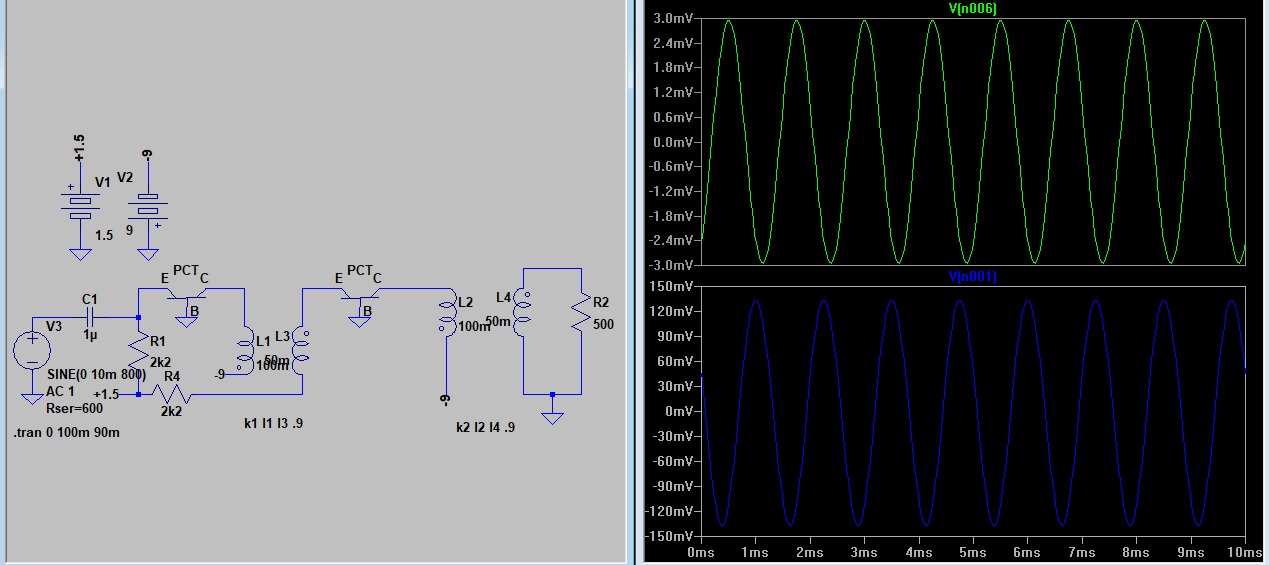
This is the input and output currents. Look closely and you can see a little jitter. (Also note the missing capacitor.)

This shot is showing the battery voltage. The batteries have internal resistance which causes the terminal voltage to vary as current swings.

The single stage amp had smooth signals. The two stage has the jitter. The battery swing from one stage effects the other.

As the battery gets used it becomes weaker because its internal resistance increases. In this sim I raised the internal resistance to shoe the effect. I varied the voltage on my test circuit and fould it would break into oscillation as I reduced the supply.
So the capacitor is needed to hold the supply steady and prevent oscillations. In the old circuits they would sometime use variable resistor in the emitter circuit. This would allow the circuit bias to be adjusted as the battery aged and give longer service life.
The SCS, SCR, and PUT are all 3 junction 4 layer devices. The difference is the pinout. The SCS device is 4 pin and can be used anyway. The SCR uses a cathode gate to switch it on and it latches. The PUT uses an anode gate which will turn the device off when not biased. The amp in the previous post is using a PUT.

It is such a small part count I will have to build one. I will use over the counter parts which are readily available. Next post I hope to have a couple screen shots with results and a part list.


