Thursday, February 23, 2023

Charging and discharging a coil to power a joule thief.

Notice the time delay when power is switched on. 

The CEMF in the coil delays the current buildup. 

The current continues to build as long as power is applied. 

When the input falls the current decays just as it increased when it was applied.

The voltage (green) reverses polarity.

The current (red falls just as it rose in the same polarity.

What you need to see here is the EMF produces current which produces CEMF opposes the current. There is a time delay as current builds and as current falls.

The inductor opposes change in current. This delay in rise and storage then delays the decay as it releases the energy back into the circuit.

How does the voltage reverse in the green waveform? The current is unidirectional and the polarity is determined by seeing the coil as a source or sink. 

(sinking)

As it is drawing power from the power source the bottom terminal is negative and the top terminal is positive. 

(sourcing)

As it returns energy to the circuit the top terminal is negative and the bottom is positive.

With this in mind look at the joule thief.

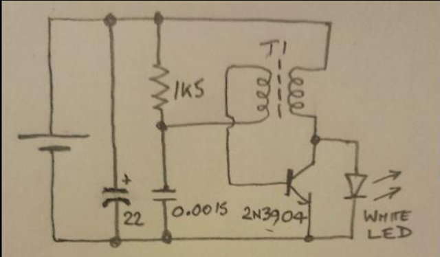
If the 2N3904 is switched on the coil is directly across the battery. The top is positive and the bottom is negative.

As the field builds in the coil it couples to the base coil and turns the 2N3904 off.

As the field collapses the current is maintained with the top of the coil negative and the bottom positive.

As you can see the diode "sees" the battery voltage and the coil voltage in series and the voltage is the sum off the two.

This is how can a "dead" cell powers a LED that requires between 2 and 3 volts.

As we know there is no such thing as a free energy (outside nuke). What we have here is energy conversion. The low voltage is stepped up as the current is maintained for a short period of time.

Power is a function of time. We dissipate 1mw of power in 1 millisecond or 1 microsecond. To produce the power the short pulse would be higher voltage or current. 

A tip of the hat to the ladies and thanks for the project idea. I can see a couple of joule thiefs in making.

Wednesday, February 15, 2023

A closer look at the joule thief or the facinating world of magnetism

 From its humble beginning 200 years ago our understanding and use of magnetism has come a long way. A short history lesson. 

The telegraph sounder was basically a relay with no contacts. When power was applied it would click. When the power was removed it would clack. The time between the click clack would be long or short and would represent the characters in the message.

click-----clack---------------click----------clack would be the letter A. Many years later we added a closed contact and fed the coil through it. This made a buzzer which was easier (for me) to copy.

The next step after the buzzer was a couple of more contacts feeding a transformer. This allow us to step up the 6v car battery to the thousands of volts needed to feed the spark plug in your car or to power the car radio (the tube sets of that day needed a 100 volts or more.


This was a marvel being able to travel and listen to the radio. It was also a battery killer. You did not forget and leave it on with out the motor running to many times (don't ask how I know this)

So everything is "NEW" and nothing is. The difference today is the transistor being used instead of the vibrator. This 'boost' supply takes 3 volts input and produces 9 volts output.


The one thing they all have in common is the inertia of a magnetic field in a coil of wire. When you apply power the coil opposes the expansion of the field and absorbs energy. When the power is removed the coil opposes a decreases in current and uses the stored energy to maintain current as long as possible. If you apply 0.5 volts through a low resistance copper wire and let the field build to its max current and then remove the source the coil will attempt to maintain the current through any path it can find. So if your source can produce 1ma through the "short" circuit represented by the transistor (switch) and the coil it will maintain that 1ma through the LED as it discharges. There is no free energy but the high voltage pulse is a short duration. The eye blends the pulses of light and it is good.

The ladies did a great job and hopefully learned things from this project that can be applied to future projects.

My latest project was a circuit to power a 12 volt LED from a USB supply. I have a solar charger for the USB supply and a boost supply much like the one above. It works but now I hang my head in shame that I bought the supply when I could have followed the ladies example.

Maybe another project in the making?

Tuesday, February 14, 2023

The DITS get younger as time passes. The Joule thief lamp as built by the new pair.

I heard from DIT and she has a pair of twins she assisted in this build. Check it out. Two more DITs.

Working with as little as 0.3 volts it will truly zap the last joule from a battery.

The finished project operating from a single C cell should function for a very long time.

I am so glad to see more designers in training!

Well done ladies.

Edit: The coils are wound bifilar.


Saturday, February 11, 2023

to regen or not to regen?

 Mr Tom on TNRB posted an interesting question.

Why will this set not perform? If Mr Andersen says it is a good performer we will assume it is. Tom says it picks up local station weakly. What makes this circuit challenging is the ferrite core. L2 60 turns tapped at 10 from the bottom. With an air core coil the first thing would be "phase the reaction". If the two coils were wound separate we could just reverse phase by reversing the wires. With a center tapped coil it is a little more difficult. 


This was the fix. Observe the base bias flow out the base and up to the diode. The .01uf cap places the center tap at AC ground. If the signal flows up the lower coil and down through the .01uf cap the upper coil can conduct in either direction without conflict. 


If the base current flows into the center tap and out the bottom through the diode the center tap is negative. The upper coil will be in conflict with the lower and provide degeneration or in phase and will provide regeneration in the other phase.

The hard question with building the circuit is how are the coils phased. L1 is the transformer primary and the 2 secondaries will have a center tapped phase aiding or opposing.

One other thing with the ferrite core would be to make the coils separate and movable. Sliding the coil along the core will vary its inductance and allow some adjustment of the tuning and the reaction.


One other possible fix would be to reverse the diode and place it between the base and center tap. This would reverse the phase of the lower coil.


Saturday, February 4, 2023

Observe the filtering requirements in the deteector circuit.

 One point I failed to stress in the last 4 post is the need for filtering. It seems to be a common practice to question the need for a choke or capacitor in a detector circuit. 
When the crew examines a circuit they seem to lean towards seeking a minimum part count. Sometimes one part will be the life of a circuit and others not so much but still effect the performance. 

If you remove the diode the circuit dies, no question. Removing a capacitor may not have as much effect. If you can tune in a station and then move the headset leads to "fine tune" it you probably should not have left out that filter capacitor. The filter will send AF to the headphones and all is well. The inductance in the headset will "smooth" some RF component in the signal but not as efficiently.


Yes the capacitors are there for a purpose.

Friday, February 3, 2023

The choice is linear or square law - Large signal or Small signal

 You need to know enough to decide between a linear or square law signal detection. The diode response curve is divided into 2 sections. The "knee" separates the 2 parts. Simply stated the knee is the point on the curve with a slope of 45 degrees. 


Below the knee the signal response is "square law". Above the knee the signal is linear. There is no way to have linear without passing through the square law region. This is another case where we "swamp" the small signal and ignore it. The signal response is based on the signal level we cannot just decide to use linear detection in a crystal set because the signal is to low.


While this circuit would be a reasonable representation for a high level detector it just is not what happens in a crystal set. Linear detection can be represented as rectification but a crystal set does not have the voltage required to turn the diode on.


This is the rest of that circuit. The amplifiers produce the signal required to turn the diode on.


Plate detection uses the non-linear section of the curve to produce higher gain on the peaks and "shifts the zero reference point from the curves mid point to develop the signal.

Now superimpose the signal over the knee and the positive half will be much higher than the negative. The signal is not rectified it is "distorted" because the positive signal accesses a higher part of the curve. This would be more like plate detection than rectification.


Thursday, February 2, 2023

Modulating Vs Demodulating Vs Mixing part 3

I adjusted the signals and cleaned up this circuit quite a bit. 


So do we want a switch or a non-linear device? The answer is yes. The next question is which? The answer is do you want a large signal detector or a small signal detector? While it is good to be able to choose we have to be aware of the conditions and available resources. If you are building a multistage receiver with amplifiers or a crystal set or something in between will determine the requirement. The circuit above has lower signals that the previous post.

Anywho. I will post data for a high signal and low signal detector for you to examine.


Modulating Vs Demodulating Vs Mixing part 2


Let's see the difference between mixing and modulating. The green wave is AM modulated and the blue is simply mixed. What is the 'real' difference? The blue is an audio reference with a RF riding on it. Just 2 signals. The green is an audio, RF, sum and difference signal. Four signals. So the question is how to turn 2 into 4 and then turn 4 back into 2?

The AM varies as the sum and difference of the 4 signals as you can see. In the mix it varies as the sum and difference of the 2 as you can see the RF ride the AF. Only 2 frequencies in the mix.

The full view. What makes the difference?

Now for the non-linear or distorted part. The most non-linear device in my parts kit would probably be a diode so insert one an look at that. It takes a few cycles to charge the circuit and then it resembles the AM signal. If that is true we should have the sum and difference. Let's take the capacitor out and see what happens.

The capacitor effect the circuit resonance. Adjusting the capacitor will improve the signal response. It bypasses RF to ground. It charges when the diode conducts and discharges when the diode is off. This action restores the missing half wave.


The cap sends RF to ground. With the coil disconnected the AF passes to the output.

Adding a diode and looking at the current we can see the pulse trains that could drive the output.

Adjusting the parts we can separate the AF or RF.

Changing the components produces the modulated RF signal. So the none linear device and filters will define the circuit.


Modulating Vs Demodulating Vs Mixing part 1

 The question comes up how does a detector work? The short answer is it requires a nonlinear device or as some say a distortion. So where to begin? First we need a signal to observe the effect on a component.

I send a pulse across a resistor and I have that pulse impressed across the resistor. 

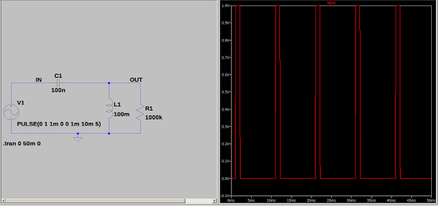
I send the pulse through a capacitor and across a coils and display the input. Clean square wave pulses.

Look at the output.

One way to check the 'Q' of a coil is to ring it and count the pulses and the wave decays.

You can check the coil self resonance using this method too.

The main object is to observe the coil will ring if pulsed.

end part 1.