If I have a 200uh coil and I want to tune 1-5 MHz what value should the tuning cap be?
1MHz 2MHz 3MHz 4MHz 5Mhz
126pfd 31pfd 14pfd 8pfd 5pfd
Now if I mark my dial the scale does not match my Vcap values. Why?


When the dial does not match we can measure the cap and calculate the inductor value.
1MHz 2MHz 3MHz 4Mhz 5MHz
129pfd 34pfd 17pfd 11pfd 8pfd
196uh 186uh 165uh 144uh 127uh
If we do not account for the strays it appears the inductor is changing value.
Maybe another series of scans with the adjusted values is in order?
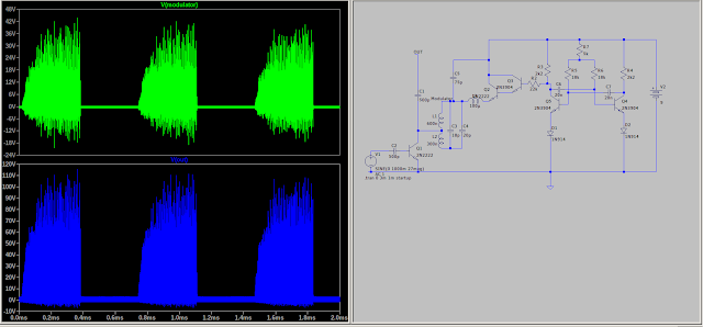
The antenna is open circuit and the standing waves are there but you can see the switching.
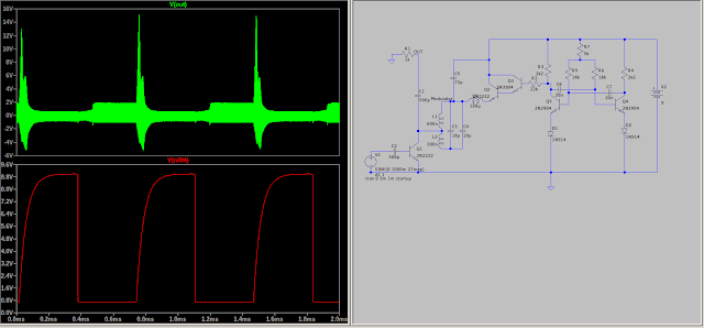
Placing a resistor for the antenna produces a cleaner out put.
I have no data on the antenna. Something else to investigate?
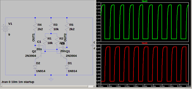
I am just putting this here before I lose it. I am locked from TRB again. A new member asked about Sinclair transistors.


It works in the simulator using 2N2222 and 2N3904 transistors and 1N914 diodes.
Silly me bought a KKMOON Dual Channel Generator. Nice little generator but it has to be programed. When I used Windows XP I could attach to it and produce a modulated signal. It was a pain programming, instructions not in English. Anywho I no longer have the program and I really want to be able to modulate the signal. My solution may not be the best but it was easy to build and works.
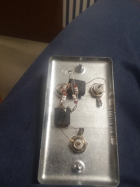
The DBM is simple to build just 3 connectors, 4 diodes and 2 transformers.
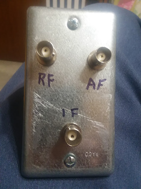
It is made on a handy box lid. The 2" X 4" electrical box makes a good rugged project box.
I tried it and it worked well.
I will make some "custom" cables.
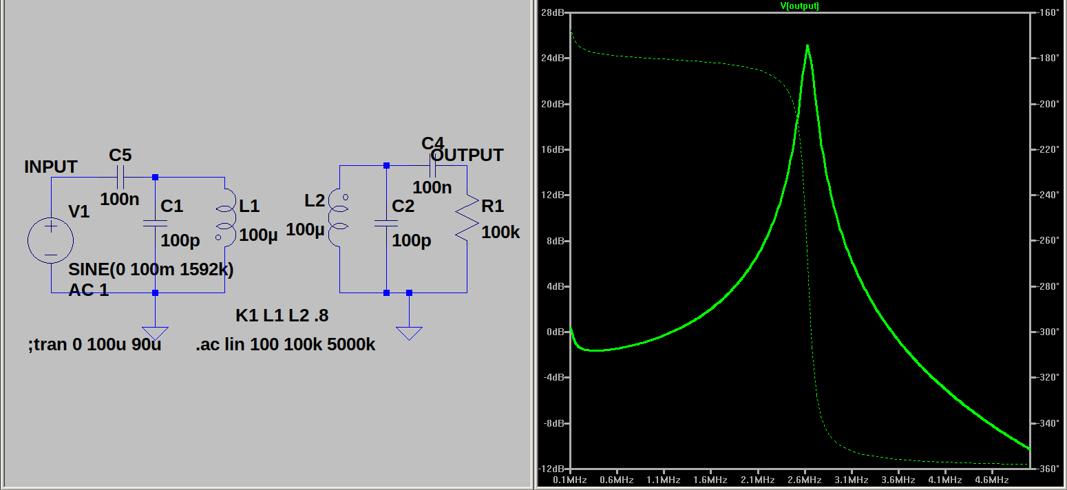
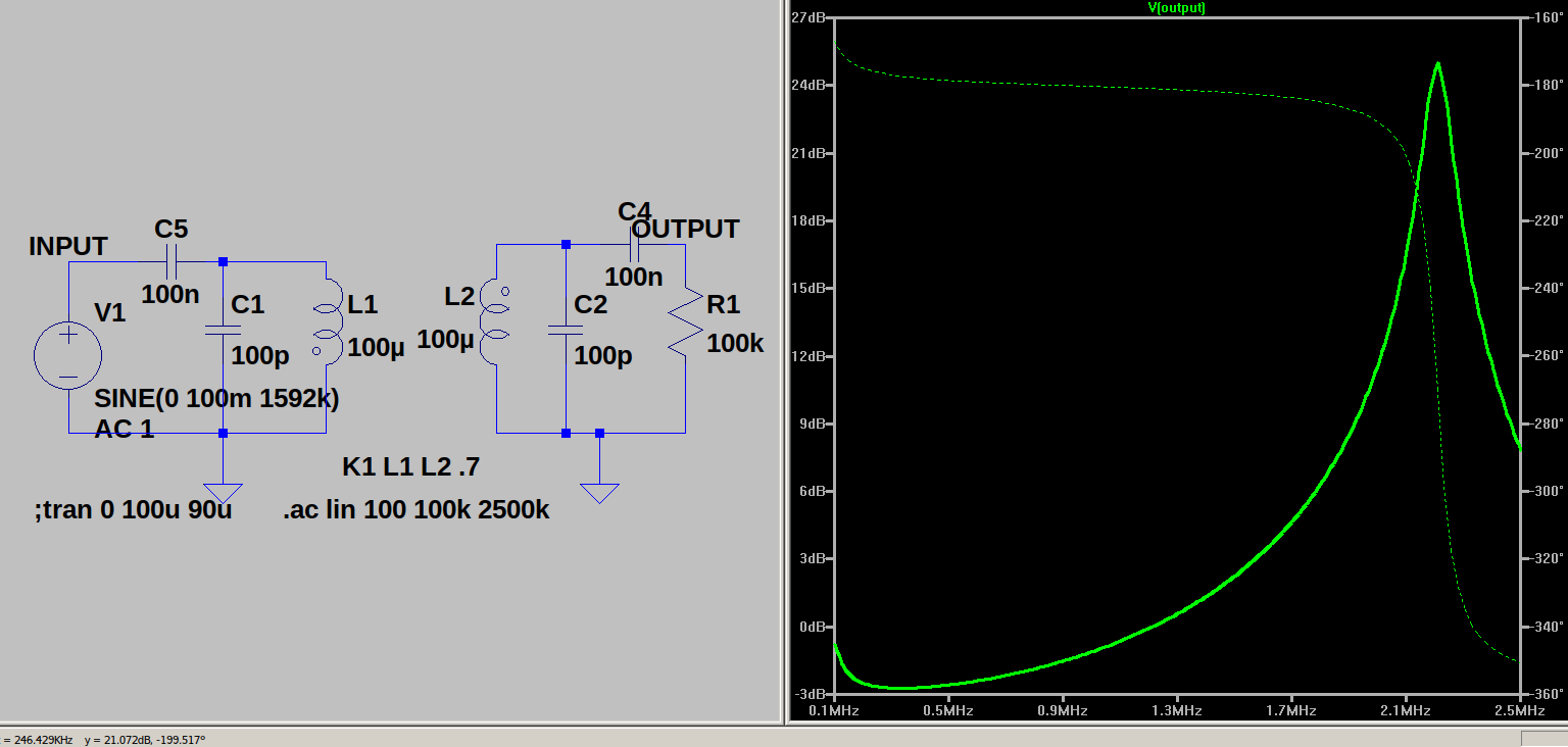
If you examined the previous post you should have observed over coupling reduces output in an IF transformer.
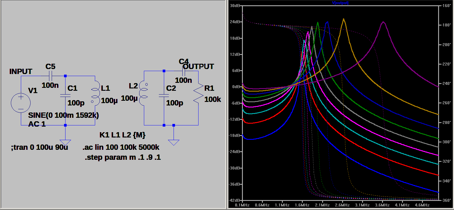
As you scan the sims observe K, OUTPUT currents. You should observe at K=0 there is no coupling. At low values of K the output picks up quickly. At high values of K the signal drops off again. You can not see the whole picture here. In the next series of sims I will show that changing K also changes the coils inductance. Loading the coil shift it inductance.
The output is half as much at K=.5 as it is at K=.25. Why is this?


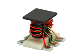
They used color coded wire which could help avoid confusion. Winding 1 coil at a time helps prevent confusion too. You need 2 of these to make a DBM.
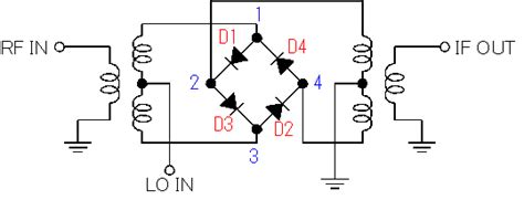
2 transformers, four diodes and a local oscillator will make a receiver. The IF will be audio in a direct conversion receiver. 2 mixers and an IF section will produce a double conversion set. Fun to play with and easy to make.