
Saturday, September 30, 2017
what determines the ring output?
Now the question is "what's going on in the ring and how to 'match' it?". When I made the secondary half what it was the output responded so the next step was to reduce it more. It seems the diodes need more current.
 In spice you can open the window menu and select set reference to set the negative probe. Here I set the probe at the center tap on the secondary. I measured the top of L2 and ground and that equals the output so whatever is on L2 - l3 is equal the output.
Consider the diode characteristics
 |
| These datasheets are available in a couple of different places. They were developed by Ben T. and Mike T. |
 |
| They show a thing called Ideality factor or N on the chart. In theory 1.000 is ideal. Look at n and Ro. |
 | ||
| I did a little cut and paste to isolate the diodes we have been using in out sims. |

 | ||
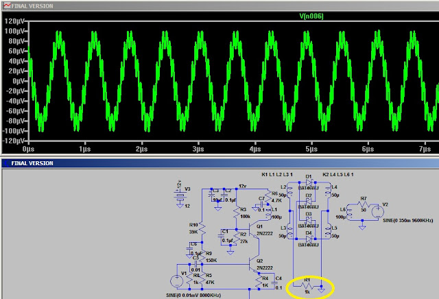
| So that brings me back here. I put reference at L2 - L3 and measure to the other end of the coils and then to ground. The output is = the voltage across L2 & L3. When R1 is about 40K the output peaks. Lowering R1 will lower the output but raising R1 has no effect on the output. |
Friday, September 29, 2017
DBM BAT-46 vs 1N34A
I have some questions about the diode selection and the feed to the AF amp so a couple of quick sims.
 BAT46 diving a 50 ohm load. (45uV)
 BAT54 driving a 1K load (100uV)
 1N34A driving a 50 ohm load (80uV)
Now for a surprise???
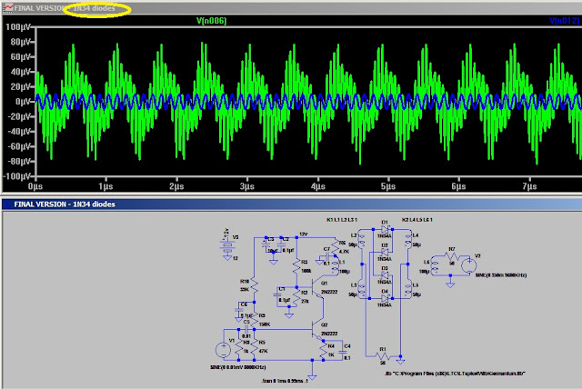
 1N34A driving a 1K load at plum new 1 mV. All I changed was the diodes and the load resistor and we go from 45uV to 1 mV. The 1N34 was developed to be used in radar some maybe it should not be a surprise that it would function well but what just happened? That thing about Z matching from a couple post back. The 1N34A is 40 - 50k Z while the BAT46 is 200K.Just to test/prove the point I put a couple 100k resistors across two diodes and .
 Notice the negative is unchanged. So armed with this info I'll try some different diodes and output loads.

The BAT54 with a higher Zo is more respectable.

D18 diode at 5K. looking good
 The 1N34A at 40k
 As a final check, the 1N34A at 400K. Notice once the load goes above 40K we see little change. So now the question is do we have some 1N34As or D18s if not how to match the output?


Now for a surprise???


The BAT54 with a higher Zo is more respectable.

D18 diode at 5K. looking good


Toroid Calculator
toroid calculator
The toroid data is in the program for a lot of common cores AND it has an unknown core function.
zipped calculator
I zipped the program so you can download it.
The toroid data is in the program for a lot of common cores AND it has an unknown core function.
zipped calculator
I zipped the program so you can download it.
Thursday, September 28, 2017
Transformer for the DBM.


So it is time to wind a new transformer. If not trifiliar then how?
How much inductance does a DBM transformer need?
In a day gone by I was taught the source Z should be 1/10th the load Z. It seems common knowledge today is Zs=Zl for max power transfer. When I was a teen the books said you get max power when Zs=Zl and your generator/battery consumed 1/2 the power, for this reason we set Zl at least 10 times Zs. With the 10 to 1 ratio we still use 9% heating the source. With that in mind and looking the manufacturer datasheets I decided to do a none scientific test using spice to see if I can find the 'perfect' transformer. Andy sent me a circuit which I used for the test. Then I built a circuit and tried it. Here are the circuits used in the test:
 my circuit.
 Andy's circuit.
The results:


I looked through several spec sheets and found coils wound wit 3 turns, 6 turns, etc. The only spec they gave was the Z at a certain frequency. The recommendation was for the transformer Z to be 4 times Zs at the lowest frequency. The test seem to support the fact that more inductance doesn't give more output. It did show that some of the circuits drew a larger current and loaded the source more.


The results:
 |
| 100 uh 10 uv in 15 uv out |
 |
| 1uh 10uv in 15 uv out |


 |
| It was looking like it could not go to low so 1ph no output. |

I looked through several spec sheets and found coils wound wit 3 turns, 6 turns, etc. The only spec they gave was the Z at a certain frequency. The recommendation was for the transformer Z to be 4 times Zs at the lowest frequency. The test seem to support the fact that more inductance doesn't give more output. It did show that some of the circuits drew a larger current and loaded the source more.
Tuesday, September 26, 2017
The DBM with homemade transformers
Making a DBM using trifilar wound coils.
 I gathered all the parts. I'm using a microscope slide as my base. I covered the top of the slide with copper foil. I'll be using 10 meg ohm resistors as my stand offs. The two cores are wound with 11 turns of 3 twisted wires. A piece of solder, 4 diodes and some rivets complete the list.
 I soldered a rivet to ground and one on a standoff at each end for the Rf and LO connections. Four rivets on standoffs for the diodes. Then put the diodes in a diamond, head to tail.
 I put 2 tie points for the output AF and install the transformers.
 The DBM and the hearing aid amp are ready to test.
 Here is a closer view of the DBM.


The second generation oscillator
Putting the second generation oscillator on board
 I printed the circuit out.
 Number all the points. Zero is ground and then just number the tie points.

I put down copper foil for ground and screwed terminal in for the tie points. I numbered them to try and not get confused. Then it was tie the components between the tie point while referring to the drawing.
 After wiring it up I put 6.2 volts on it and got 383 mv Pk-Pk with a one turn feedback.


I put down copper foil for ground and screwed terminal in for the tie points. I numbered them to try and not get confused. Then it was tie the components between the tie point while referring to the drawing.

The second version of the oscillator using 2N2222 transistor
Andy's oscillator version two
 I 'built' the oscillator in spice with good results. I did discover to much feedback is easy to obtain. If you step L2 up in value it will not be long before you discover its limit. I took a short lead and made a single turn coil in the core I intend to use and it had .3uh so there will be a need to not be to zealous with the feed back winding. 2 or 3 turns should do.

Playing with the RF Amp in spice
The sim will run faster if you set the display time to a smaller value. I made that change and will point it out when I post the picture. That run took about 5 minutes to load before I changed the setting. Ok back to the DBM LO requirement.
 The level 7 will be .7 volts peak. Now let's look at the oscillator.
 I have built the one on top of the page. I plan to try the other when I get some shop time. The one I made produced about 250 mv so it will need a little boost. I posted the model for a RF amp in my last post. The last line in the post. The questions are will it produce the output level we need and at what frequencies will it function. If it works as desired we can build the oscillator for the frequency range we want to receive.
 Notice I set the input at 50 mv and 10mhz. So at 10 mhz we should see greater than .7 volt peak.
 At 20 mhz it has dropped off a bit but still good.
 At 30 mhz dropped some more but still good. Note the orange circle. It took 5 minutes to run this sim and I lowered the time for the viewing window. With the new times it loads in less than a minute. Shortwave is generally 3 - 30 mhz so it should be good for our set but I had to do one more test to push it limit.
 At 100 mhz it is still providing some gain.
The transformer I'm using in the sim is a tri-coil supplied by BG Micro. The little coil is 25 cents each and works well. You can wind your own but will have to adjust the values to fit. I wound a Fair-Rite T50-43 with 11 (trifiliar) turns and it measures 60uh per winding. Substituting the value for the transformer will tell the story about the transformer requirements. That will be a project for later.
NOTE: I made a DBM with the Fair-Rite cores and 1SS98 diodes and it did function when driven with my signal generator.
Subscribe to:
Posts (Atom)