Sunday, November 26, 2017

Adjusting the supply on an amp to see the effect.

A request was made for a 1.2 volt amp. The idea was to make a radio powered by a single rechargeable cell. My last three post were in response to that question. Tonight I will present a the amp with different supplies to see how it would work at higher voltage levels.
The input will remain at 10 uv.
Here I adjusted the components and have 850uv output at 1.2 volt in.
I raised the power supply to 1.5 volts and get 1.45 mv out.
Here I make the big jump to 6 volts and get 12 mv out.
At 9 volts we get 20 mv out.
At 12 volts we get about 28 mv.
With the same circuit there is quite a change in output when the supply is varied.
The goal of a 1.2 volt supply radio is possible but it would be a lot easier to use 1.5 volt or more.

Wednesday, November 22, 2017

modified amp for more gain

I made a couple of change to the resistors and added gain.
10 microvolt in and 1350 microvolt out.
This cost me 3 ma battery draw.


Tuesday, November 21, 2017

Did a sim on the amp I posted last night.

I located My model for the P416B transistor and did a simulation. I did the sim at 2 MHz and 10 micro volt input.
Here I am probing C2.

Here I am probing C4. 10 micro volts input gives about 850 micro volts output.
My test gave better results than the sim? My model may be a little off. Close enough for me though. Anyhoo, it is one possibility for a 1.2 volt amp. The builder could possibly improve it by tweaking some component values.

I made the board last night with sockets so I can test the response of different transistors. It was not designed to be optimized for a specific transistor. I have some old tarnished ones I can not read the numbers on and thought I would use a couple in my AF amp for the AER. Chances are I'll stick with the K669 or BF2040. So many choices, so many circuits to build and test!
The fun is in the build so just build something.


1.2 volt RF amp


The power supply is set at 1.2 volts. The two meters are on the input and output. I switched the meters to assure they were not giving false indication due to calibration errors. I did some readings on the millivolt scale and  some on db.
The generator is set at 1 MHz.

Sunday, November 19, 2017

Looking at another oscillator - FM transmitter oscillator

I was shopping for some reasonably priced high frequency RF transistors and found a link to some TV tuners. The oscillator in the UHF section was interesting.
TR6 is a BF970 high frequency, high gain, low noise transistor. It is rated 1 GHz so it should serve us well in a .3 - 30 MHz set. Another search lead here.
Once again the transistor is a BF970 which is being used for a FM transmitter. He says a range of 200 meters with a 12 volt supply. This circuit would be perfect for a multi band set  because the coils is not tapped and feed back is through the capacitor. Time for a simulation.
That little circuit is singing at 8 volt peak to peak. I don't have the model for the BF970 but I tried three transistors and they all worked. This was the strongest. So time for a build.
This is my scope trace for the circuit built with a Germanium transistor I had on hand. Just under 4 volts peak to peak and 489 KHz. I had three coils I tried which oscillated at differ frequencies.
I replaced the Germanium transistor with a Silicon transistor and used a smaller coil. I think the bias could be adjusted to improve it. My proof of concept worked with three coils and a Germanium and Silicon transistor so I think it is a keeper.
The good news on the transistor is you don't have to take your TV apart to get one. You can find them on E-Bay at a reasonable price.
$2.72 for 20 here:
 BF970 on E-Bay
 They will combine orders into one shipment so browse the store before hitting the buy button.

Sunday, November 12, 2017

Frequency spectrum and temperature, including RF and visible light

This is just a response to a recent thread on TRB involving telecom via light bulb. It may be interesting but is just a collections of facts that the reader can use to draw their own conclusion. First I'll travel back about 60 years and relate some personal history. My grandfather was a working blacksmith, he had a shop until I was in my middle teens. It would be interesting to watch and try to understand what he was doing. Among other things he made knifes, some of which are still being used. He could look at the color of a piece of steel in the forge and tell you within close tolerance what its temperature was. He knew from experience what this chart tell us.
As you can see the steps are in 100 degree F steps. He could tell just what shade he wanted before quenching the metal to make a spring or a bolt etc.
The interesting thing is the chart can be extended to include a much broader range of frequencies.
 Here we see radio and TV waves are the same electromagnetic wave as visible light but at different wavelengths. Here is the cool thing. Any body being heated will radiate the waves and the frequency can be defined by the temperature. What? Yes if I could devise a way to direct the waves to my radio I could tune it to a blank spot on the band and heat an object to produce a signal it could receive. I can hear the nay sayers! This is why I'm not posting on forum. I may be dumb as a box of rocks but not stupid.
So what is/was the application?
Here we see a filament in an electric lamp. Notice it is not just a piece of wire it is a coil which has been stretched to form a helix. Not a straight helix but a wiggly helix yes?

 Now we jump up on the roof and find an interesting antenna. Observe the helix is very similar to out bulb filament. Much larger and straight. It should be noted that helix as this one will radiate or receive from the end. Because it is designed to send or receive satcom. It could be used for omni directional com also but would be designed at different dimensions.

Yes the rubber ducky is a helix sized for broadside or omni directional com. So let's look closer at the pen light bulb.
Notice the filament is still a coil but now it is straight. (I show this one because you can see the filament)
This is the one being used for the transmitter. If you look you can see the filament. Might require a little imagination. Now apply the info and consider
1. As the wire heats it will radiate visible and invisible electromagnetic signals.
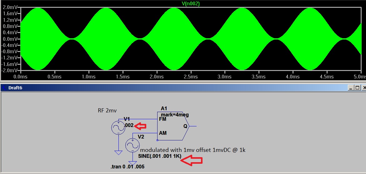
2. If the power to the light is varied at an audio rate it will cause the frequency to swing at an audio rate. This is what we call a Frequency Modulated wave.
3. Consider grandads chart, 100 degrees produces a different color. Less than 100 degrees will produce enough frequency swing to detect. BUT that's not all of the story.
4. There is a thing called thermal ionic emission. As electrons are emitted into the void in the bulb that can create EM radiation.
5. Another character at play here is Skin Effect. True as the filament heats it produce changes in the wire resistance. As the frequency changes it produces changes in AC impedance.
6. Remember the rubber ducky antenna? Looking at the filament as a rubber ducky can produce an image of it radiating RF.


You can see from this chart the RF spectrum is as broad as a football field and as small as an atom. The amazement here for me is not that the bulb can radiate a signal but that someone developed a receiver that was able to receive it!
The plan was to modulate a light beam but the bulb response was to slow because of its mass. The receiver was able to distinguish frequency changes in the RF spectrum.
That's my story.


Thursday, November 9, 2017

Wound a DBM with a binocular core today.

I sure could use some 10 year old eyes and nimble fingers for this one but it was well worth the effort.
I'm using a SMALL binocular and #34 wire. The build begins with 3 wires twisted together.
I put it on the ruler so you can see the size.
You make a hair pin and pass one end through each hole. Leave a loop long enough to do your hookup.
After making 8 passes through the core on each side I unravel the wires. Yes that #34 is quite small but I could not get more than 8 or 9 passes through the hole in the binocular.
I have all the wires untwisted and am now looking at 12 wires. After stripping a little insulation from the ends I can use my ohmmeter to ring them out.
Before I start ringing wires I need a place to put them. There will be 4 diodes in a ring, a RF input, a LO input and an AF output. The AF will have a ground and it will tie to the center tap of the LO transformer so I just used the LO input for it.
I put the core on the block with a piece of double sided tape and a pin at each tie point
Now I use the ohmmeter to find a coil. The first two wires that ring out will be my input.
So I put a winding on the RF and a winding on the LO. This leaves 4 leads (2 coils) on each side. I check for a coil and then use one end to tie with the free end on the other end of the core. This give two coils in series. the two tied together will be the center tap. One center tap is AF output and the other center tap is ground.
Now a little solder on each pin for the diode ring and put the diodes on them.
The finished product. It is not as pretty as a store bought one but it works pretty well. It does need a 7dbm drive (.7 volt peak).

Monday, November 6, 2017

An AM signal in SPICE

Look in the special function lib. The last 4 items all the way down the list.
Select modulator add two signal sources.
Right click the modulator and add the two descriptors.
Mark= ?????
Space= ?????
The ?????= your desired frequency.Be sure to put both are your signal will be distorted.

V1 is the amplitude of the envelope.
V2 is the modulating signal. Set its DC offset, amplitude and frequency.
Q is an AM signal you just built.

Another sim for the DBM with 100uv input

With 100 uv in the output is the smaller waveform.

The AF output.
Notice I have resistors bypassing the diodes. They don't seem to reduce the output until they are very low value. From 470k to 47k show little change.