Saturday, July 21, 2018

Pulsing and ringing a coil (or earbud)

The question is what would it sound like. My best guess is it would be good since the circuit was presented in magazines and data books but the debate is on going. Let's look at at couple of factors. My first question is why use the unijunction? If we drove the speaker directly from multivibrator how would that work?
The data I present is for an earbud but would apply to any coil. Remember the coil has resistance, inductance and capacitance and therefore has self resonance.
If you pulse with a single spike the coil it will 'ring'. It will oscillate at its resonant frequency and the signal strength will fall off as show above.
If you pulse it with a square wave it will ring as above.
The coil is being pulsed at a low frequency and rings at its resonant frequency.
The pulse frequency has been raised so the ringing forms the sine wave and re-enforces it before it drops off. So you should be able to see the coil will 'shape' the wave and the self resonance of the coil will be the controlling factor. Now the question is 'what is the resonant frequency?'.
This is from a headphone spec sheet. It show the phase angle and impedance. Remember the phase angle is 0 at resonance. so we see resonance at 100 Hertz. If we pulse at a rate less than 100 hertz we have ringing above 100 hertz the next pulse arrives before the coil produces a full cycle and thus no ringing.

This is the response of the unijunction transistor. The 47K resistor and 22nfd cap trigger the unijunction. In the circuit above the supply is DC. In the circuit being discussed the supply is a square wave.  It could be said the multivibrator is unnecessary and redundant. Connecting the battery directly to the top of the 47K resistor will produce a tone. Using the square wave supply will produce a tone control by controlling the charge rate of the 22nfd cap. Does the cap charges in one cycle by the multibrator or 10 cycles? That is the question!

Saturday, July 14, 2018

3 stage AF amp using the Fair radio interstage transformers

 The third line down is the transformer I wanted but I didn't want the $66 price tag, ouch!!
I shopped at Fair radio a little and found this one.
At $2 it was a deal. This is an older one with the same spec's.


This is the circuit I used for my hearing aid amp. It would be a good place to use a couple of the transformers. T1 and T2 are interstage and T3 is an out put transformer. I have a box of them I picked up for 30 cents each at a surplus sale a while back.

The output transformer is not necessary but I don't like putting my headphone in the DC circuit.
I put one on a piece of poster board to see if it was as good as I thought it might be. It was better! It needs the volume pot. Touching the input will buzz your ear.
I put my audio generator on the input and it sang with it barely off minimum output.
Time to find a box and a board for a permanent build.

This is the circuit I used before. I used GS109 and MP40 transistor with good results.


Thursday, July 12, 2018

2 transistor radio in sim

The circuit asked about
The sim. I added C3 and R4 so I could read the output with a zero reference. .1mv in 5mv out. The transformer is step down so the output current level is higher with the lower voltage. Chances are the loading produced by a mismatch would not produce the same output level without the transformer. food for thought? (maybe another sim should be ran with RC coupling?)


Wednesday, July 11, 2018

building a JFET amp no math just logic

I'm going to piece together an audio amp to drive my Low Z earbud and my Hi Z earbud without any math other than in my head (guessing).
I selected the 2SK2539 simply because Arrow.com sells a 3000 reel for $15 dollars with free shipping. A reel should be a lifetime supply for an amateur. You can use whatever JFET you have on hand. The first step is to determine the Q point. I put a 1K resistor in the source circuit to set the bias and a 100k to tie the gate to the circuit. I wanted about 1 ma. This gave me just over 1 ma so far so good. The drain needs room to swing so I select a drain resistor that will drop about half the supply at 1 ma. 4.7K should work nicely. so ready for the next step.
Hows that for dumb luck? The drains Q point is about 4 volts. Now to try some signals to see how it functions.
1mv in 800 mv out.
3 mv in 2 volts out, starting to distort.
5 mv in flat topping. Now to look at some loads. I have standard earbuds which are 60 ohms and a high Z earbud which is 2K. I will make and output port for each.
Yea that will drive my earbud to hard. I am hard of hearing but I can still hear thunder;).
Yes the Hi Z phone will work too. I have some transformers and will probably put one here but it will work without it.
Time for a build!

Saturday, July 7, 2018

Probing the colpitts circuit in SPICE

If you load the oscillator in LT spice and run the sim it can help understand how the circuit works.
 I set the coil resistance as 1 ohm and the reference at the bottom of the tank.

I adjusted the coil resistance until it killed oscillations. You can see the signals levels falling as you come down the sequence. It was a good exercise in SPICE. I will have to build one on board and see if it will sing for me.

Friday, July 6, 2018

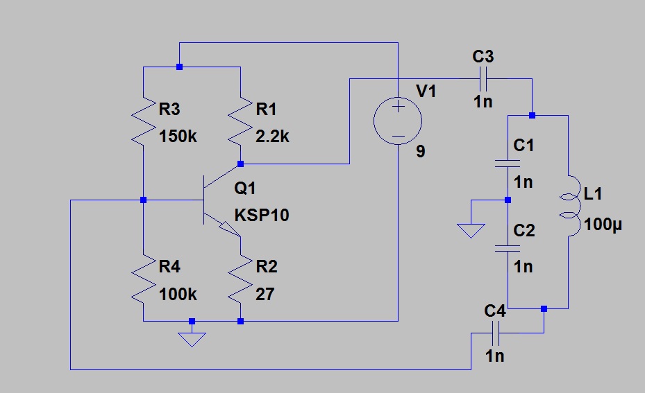
colpitts oscillator

The teacher says build the DC bias network first. This is it. In order to have an oscillator I need a resonant circuit.
L1, C1 and C2 are the tank. Capacitors in series add as resistors in parallel so I have a 500pfd cap a 100uh coil forming my tank. This will give a resonant circuit at about 712Khz.
I take a signal from the collector and feed the tank. Then send feedback to the base. That is C3 and C4s jobs.
Now I power the circuit and it sings. It is producing a 8 volt pk-pk signal. Lowering the value of C3 and C4 will produce a lower output. Lowering C3 will reduce the feed to the tank. Lowering C4 will produce less feedback to the amplifier input. In order to have oscillation we need a gain higher than 1. It simply has to overcome the circuit losses. If we had a load on the tank we would need more feedback to replace the signal drawn by the load.

The capacitor divider divides the AC voltage the same as resistors will DC.


You should have no trouble seeing the resistors as a voltage divider (for a DC circuit)


The capacitors provide the same function in an AC circuit. The reactance is set by the frequency. The series circuit has the same frequency so we can use the ratio of capacitance and do the division. Xc = 1 / (2 * pi * f * c) so the larger c has the smaller drop.
Vc1 will be greater than Vc2. With resistors  we use a formula such as Vr1 = Ea * (R1 / (R1 + R2)).
With parallel resistors we use:
Rt = 1 / (1/r1 + 1/r2 .......) When we do this we are applying Ohm's law and assuming a voltage of 1 volt.
I=E/R Ir1=1volt/r1 Ir2=1volt/r2 It=Ir1+Ir2 R=E/I
Rt=1volt/It. See it is Ohm's law assuming 1 volt applied.
 You can solve the capacitor circuit using the same approach BUT remember capacitor in series add as resistor in parallel so use the conductance to solve it.


Tuesday, July 3, 2018

measuring the input Z

You could place a pot in series and adjust Vin to 1/2 Vg then the pot would be equal to Zin. If you use this approach and do not measure both points as you adjust the pot you will have an error 600 Ohms. Remember maximum power transfer is at the half power point. If Zin = Zout the drop across Zin is 1/2 the supply. In this case Zin=Rg + Rs. So the point where we match the impedance is not determined by the pot alone.
I have the generator set to 10mv and have a measured Vg = 9mv I'm losing 1mv across the gen resistance.
Here I reduced the resistor and read Vg and Vin.
I increased the resistor and measured Vg and Rin.
The point where Rs = Zin would give the best results. Setting Rs to drop 1/2 Vg gets us close to that point but Vg varies with load so it is a juggling act. Using two meters and adjusting for the same reading could be an acceptable alternate.