Friday, February 3, 2023

The choice is linear or square law - Large signal or Small signal

 You need to know enough to decide between a linear or square law signal detection. The diode response curve is divided into 2 sections. The "knee" separates the 2 parts. Simply stated the knee is the point on the curve with a slope of 45 degrees. 


Below the knee the signal response is "square law". Above the knee the signal is linear. There is no way to have linear without passing through the square law region. This is another case where we "swamp" the small signal and ignore it. The signal response is based on the signal level we cannot just decide to use linear detection in a crystal set because the signal is to low.


While this circuit would be a reasonable representation for a high level detector it just is not what happens in a crystal set. Linear detection can be represented as rectification but a crystal set does not have the voltage required to turn the diode on.


This is the rest of that circuit. The amplifiers produce the signal required to turn the diode on.


Plate detection uses the non-linear section of the curve to produce higher gain on the peaks and "shifts the zero reference point from the curves mid point to develop the signal.

Now superimpose the signal over the knee and the positive half will be much higher than the negative. The signal is not rectified it is "distorted" because the positive signal accesses a higher part of the curve. This would be more like plate detection than rectification.


Thursday, February 2, 2023

Modulating Vs Demodulating Vs Mixing part 3

I adjusted the signals and cleaned up this circuit quite a bit. 


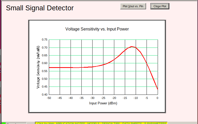
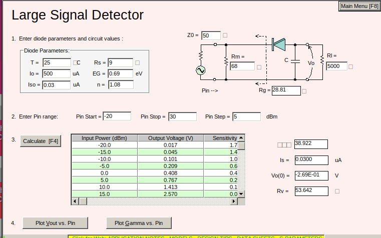
So do we want a switch or a non-linear device? The answer is yes. The next question is which? The answer is do you want a large signal detector or a small signal detector? While it is good to be able to choose we have to be aware of the conditions and available resources. If you are building a multistage receiver with amplifiers or a crystal set or something in between will determine the requirement. The circuit above has lower signals that the previous post.

Anywho. I will post data for a high signal and low signal detector for you to examine.


Modulating Vs Demodulating Vs Mixing part 2


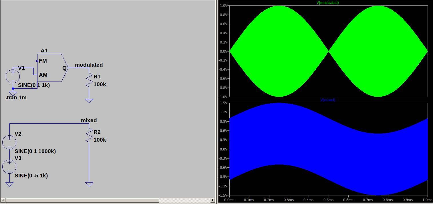
Let's see the difference between mixing and modulating. The green wave is AM modulated and the blue is simply mixed. What is the 'real' difference? The blue is an audio reference with a RF riding on it. Just 2 signals. The green is an audio, RF, sum and difference signal. Four signals. So the question is how to turn 2 into 4 and then turn 4 back into 2?

The AM varies as the sum and difference of the 4 signals as you can see. In the mix it varies as the sum and difference of the 2 as you can see the RF ride the AF. Only 2 frequencies in the mix.

The full view. What makes the difference?

Now for the non-linear or distorted part. The most non-linear device in my parts kit would probably be a diode so insert one an look at that. It takes a few cycles to charge the circuit and then it resembles the AM signal. If that is true we should have the sum and difference. Let's take the capacitor out and see what happens.

The capacitor effect the circuit resonance. Adjusting the capacitor will improve the signal response. It bypasses RF to ground. It charges when the diode conducts and discharges when the diode is off. This action restores the missing half wave.


The cap sends RF to ground. With the coil disconnected the AF passes to the output.

Adding a diode and looking at the current we can see the pulse trains that could drive the output.

Adjusting the parts we can separate the AF or RF.

Changing the components produces the modulated RF signal. So the none linear device and filters will define the circuit.


Modulating Vs Demodulating Vs Mixing part 1

 The question comes up how does a detector work? The short answer is it requires a nonlinear device or as some say a distortion. So where to begin? First we need a signal to observe the effect on a component.

I send a pulse across a resistor and I have that pulse impressed across the resistor. 

I send the pulse through a capacitor and across a coils and display the input. Clean square wave pulses.

Look at the output.

One way to check the 'Q' of a coil is to ring it and count the pulses and the wave decays.

You can check the coil self resonance using this method too.

The main object is to observe the coil will ring if pulsed.

end part 1.


Wednesday, May 25, 2022

Feeding the receiver. Combining the last few post. Artificial ground increases receiver output.


Using my new (to me) Emerson as the example. The new set is a couple years older than me, about as old as dirt!

Anywho look at the antenna coil. It is a spiral connected to the input circuit in parallel with The tuning capacitor. The parallel circuit presents a high Z to the input.


The actual loop antenna looks something like this.

Look at the dotted line in the schematic. This is a single loop primary for the external antenna to connect to. When you attach an antenna and ground to the loop it will be a short circuit and have the highest possible current through it. Notice the 2 screws (center left). They are the antenna and ground connections. If you want to really soup up the receiver you could add a loading coil or artificial ground to the input loop.


Suppose you have the input loop forming a series resonant circuit which is feeding the parallel resonant tank in the converters grid circuit. The series circuit presents a very low Z and allows max current flow. The parallel resonant tank presents a high Z with minimum loading on the antenna. Remember from the last post the highest power transfer is when Rin << Rload. A short feeding an open would be ideal.

My car radio will find 2 or 3 stations when I scan the AM band.

This old set finds stations from one end of the band to the other. 

 NOTE:

A little extra data while it is on the screen. Look at the filament circuit. See the pilot lamp in the filament circuit? It serves more purpose than lighting the display. The notes give 2 sets of reading. One with and one without the pilot lamp. The lamp burned out while I was working on the set and it happened as they said it would to cause the circuit reading to vary.

I point this out because we had this discussion an the radio board before and the experts denied the facts as presented here. The notes and real life test agree.


Friday, May 13, 2022

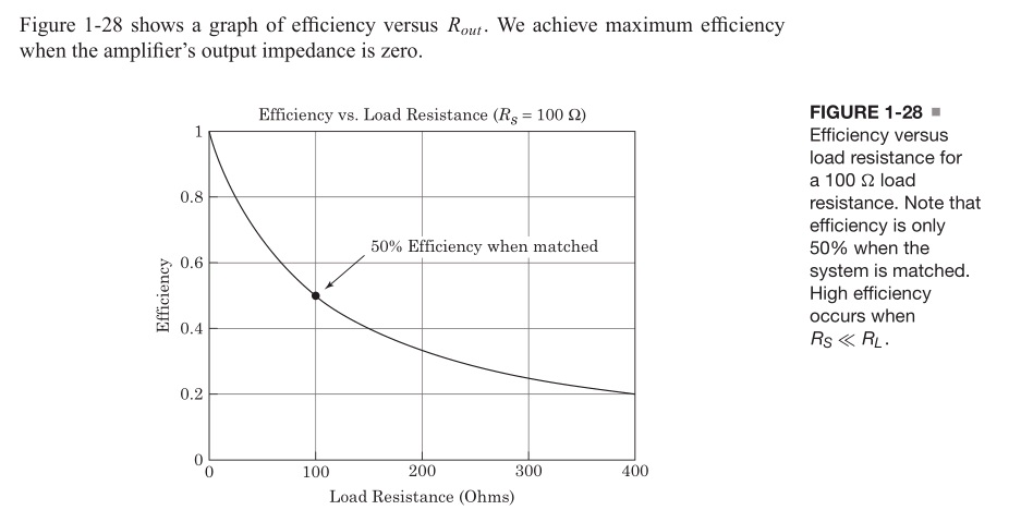
Another look at power transfer.


Note high efficiency occurs when Rs<<Rl.

P = I^2 * R therefore low Rs = low lose and high Rl = higher power out.

 Simple enough with resistive  circuit.


Now consider the AC circuit. ONLY resistance consumes power. Reactance absorbs and releases power. Z matching does not means setting the input and output equal, unless we want to lose half our power in the source. 60 years ago we would neutralize a circuit which meant adjust for phase shift. Reactance produces phase and imaginary power. Zero phase shift means resistive load and true power dissipation. So neutralize the circuit and set the phase angle to zero to get power transfer.

60 years ago neutralize the circuit. Today conjugate the reactance.  In neither case are we setting Ri = Rl.

Food for thought.

In the last post I said "TUNE" the ground and "TUNE" the antenna.

Would be better to say NEUTRALIZE the circuit reactance.

R + i0 feeding R + i0 provides maximum power transfer. 

Low R feeding high R for best efficiency.

Years ago the device was named a tuner and that is how we describe it. 


Tuesday, March 8, 2022

Artificial Ground or Tuning the ground or neutralizing the reactance in the ground loop.

 The antenna tuner can have a section to tune the antenna and a section to tune the ground. You can search and find several commercial products and some created by hams. They are mainly for transmitter applications but could help a receiver too. Some popular home brew sets have tuners with matching. Anywho I assembled a little monitor and ran some test on my 7 foot whip using the chassis ground on my DX-160.


It is fairly simple but does a good job. I am using the NanoVNA to sweep the circuit but you can use a signal generator. The sweep allows the operator to see where he is on the curve a fixed frequency will require a little searching. 


The antenna lead is simple threaded through the core. The core was from a core test. It was wound and tested to see the core properties. I did not count them but about 15 - 20 turns. I did measure to coil. It is 100uh. The meter is set to 50ua. You could use a DVM set to its lowest range. Use the pot to adjust the reading. (keep it on scale)


This is the circuit I used. The blue is RF. The lighter trace is DC output.I am using nanovna-saver to control and monitor the test. The program attaches to the vna, displays and records data. In the following shots I tested the whip against ground and then added a Vcap in series with the vna and ground. You will see the dip shifting as I change the Vcap setting.


When I have more time perhaps a dual circuit to monitor the antenna and the ground?  

Tune the antenna with a PI network and the ground with a series LC?

That would require 3 or 4 Vcaps and some tapped coils. I thinking a simple arrangement would consist of 3 or 4 (yellow/white) cores with 1T, 2T, etc. and 3 or 4 (green) cores with 1T, 2T, etc.

I did a test board with 6 green cores and found the following reading at the taps.

1- 2.5uh

2- 12.8uh

3- 29.8uh

4- 68.7uh

5- 133uh

6- 213uh

It could use a switch or simply a clip lead to select the tap.

Um? more on that later.