Saturday, May 11, 2019
micro strip transmission line used in Z matching????
The sim is mapping the transmission line Z.
This could be any insulator separating a strip of foil from a ground plane. I will be using a 1" strip 1/8" and 1/4" wide.
The glass could be a microscope slide or a glass from a picture frame or a window pane. The paper could be the back of a picture frame or a piece of press board. A single sided circuit board might be good. The problem is the thickness of the insulator and the width of the foil.
An example circuit that could use a couple of transmission lines.
This could be any insulator separating a strip of foil from a ground plane. I will be using a 1" strip 1/8" and 1/4" wide.
The glass could be a microscope slide or a glass from a picture frame or a window pane. The paper could be the back of a picture frame or a piece of press board. A single sided circuit board might be good. The problem is the thickness of the insulator and the width of the foil.
An example circuit that could use a couple of transmission lines.
Friday, May 3, 2019
Matching load to Rc
Food for thought, low current circuit with Rl set to match Rc. This circuit would be easily overloaded as the sim shows.
Give and take. More current allows lower Z circuit. Lower current circuit produces higher voltage gain. Remember we have a DC circuit and an AC circuit. What if you bias the circuit for a high current and the use an inductor for the load? The slope of the DC load line would be "vertical" and the AC load line would have more slope. Just something to consider.
Tuesday, April 30, 2019
power consumption vs power out. vs voltage out
The "rule of thumb" is that the output of an amp is equal to Rc. If this is so then making Rl = Rc will give the Z match for maximum power out. We need to consider is the transistor a voltage amp or a current amp. You can look at it as a voltage controlled resistor OR a voltage controlled current source. We need to consider the frequency and the need for stability too. I generally like to make low voltage and low power circuit to operate on battery power. This influences the design too. First a series of screen shots to consider.
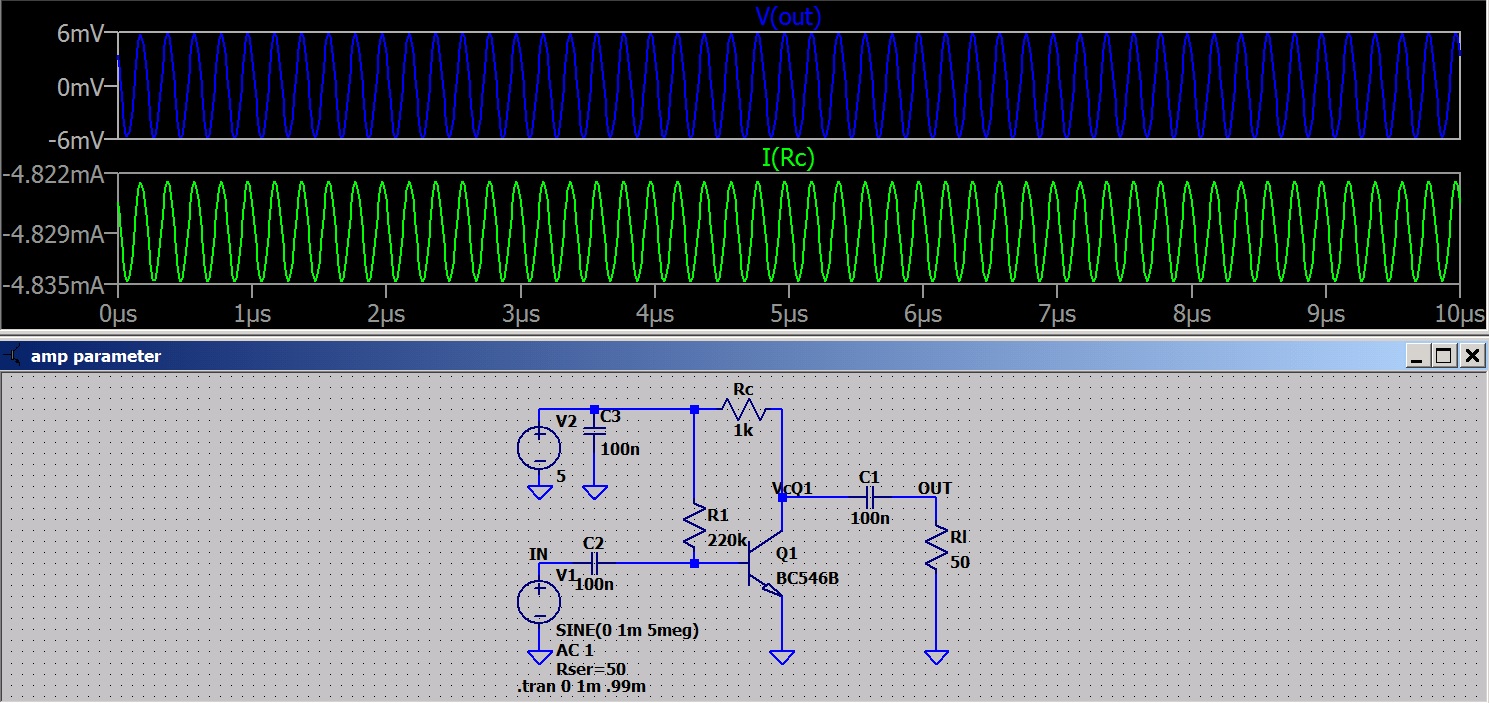
How much Ic do we want. The last two shots have the same power out BUT one is 10ma and the other 50ma.
Some food for thought?
Edit: Look at some RF 50 Ohm amps and you will find most run at about 10 ma Ic. This seems to be the compromise for Z matching and power consumption.
Audio systems were designed for 600 Ohm allowing lower currents and power consumption.
At RF the lower Z helps overcome circuit reactances. In a microwave circuit a wire running a fraction of an inch above the ground plane will have inductance and capacitance and the circuit is more critical. I'm working in the HF range which is more forgiving.
As I said food for thought.
![]() |
| Here I set Rl = 10Rc. 80mv output with 1mv input is reasonable. Look at Ic and RQ1. |
![]() |
| I set Rl = 10RQ1 the power output increases. What's up with that? Vout is unchanged so it must be a current change? |
![]() | |
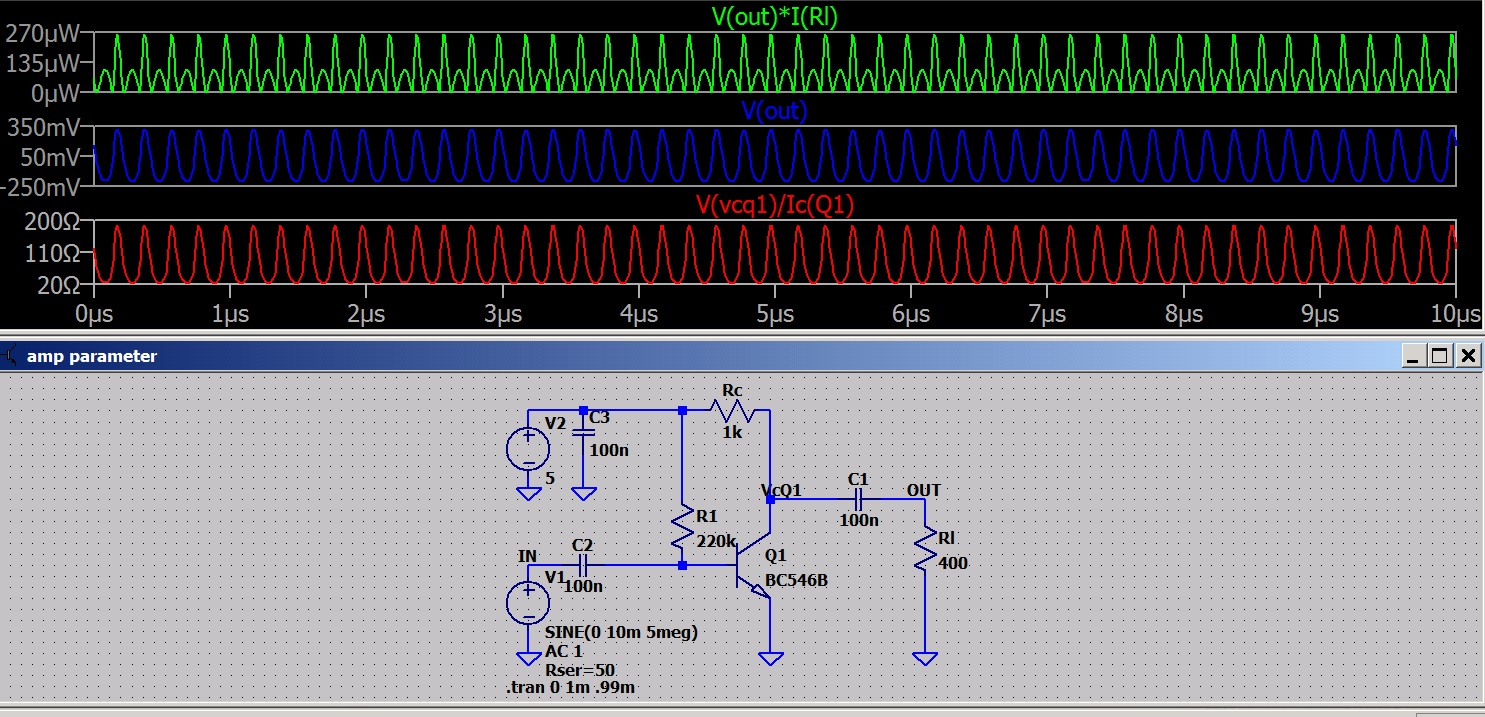
| I set Rl = Rc and get the higher output. It appears making Rl = Rc gives a higher power output and making Rl = 10Rc gives a higher voltage. |
![]() |
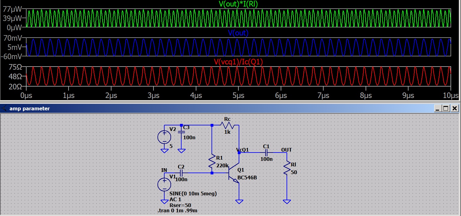
| Wait a minute! setting Rl = RQ1 gives a higher power output than when Rl = Rc? |
![]() | ||
| In the previous circuit the transistor was dissipating half the power. This one is producing more output without heating the transistor as much. |
How much Ic do we want. The last two shots have the same power out BUT one is 10ma and the other 50ma.
Some food for thought?
Edit: Look at some RF 50 Ohm amps and you will find most run at about 10 ma Ic. This seems to be the compromise for Z matching and power consumption.
Audio systems were designed for 600 Ohm allowing lower currents and power consumption.
At RF the lower Z helps overcome circuit reactances. In a microwave circuit a wire running a fraction of an inch above the ground plane will have inductance and capacitance and the circuit is more critical. I'm working in the HF range which is more forgiving.
As I said food for thought.
Monday, April 29, 2019
Sunday, April 28, 2019
Now some Z matching questions
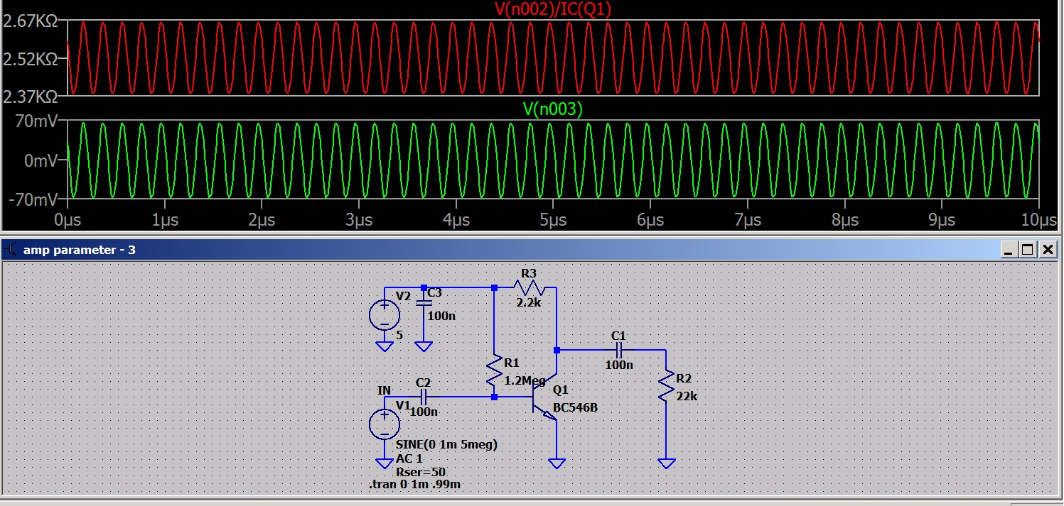
The rule of thumb for small signal amps states that Rl should equal Rc. As you can see The transistor Z which is Zgen in my circuit is equal Rc WHEN Vc is set to one half Vcc. Rc and Z transistor form a voltage divider and therefore are equal when Vc is equal 1/2 Vcc. The shot ahead of this one shows the output is higher when Rl is larger than Rc.
So the question to be asked before designing the circuit is do we want voltage or power gain?
How much collector current shall we have?
What will the load Z be?
Subscribe to:
Posts (Atom)