The circuit that was offered.
I like to use connect the dots to do the hook up so First thing I did was number the terminals. (it also helps with referencing the circuit since the components are not numbered)
I made the circuit as presented except I used 2N2222 transistors and 33ufd caps.
I did some voltage checks and recorded them on the drawing. I did not like seeing the center transistor with no emitter resistor. Its base emitter voltage is the first transistors collector voltage. Seems kind of low? So let's look at the circuit with the scope.
I have the scope on the head phone connection with an 16" test lead for the antenna. Yes my local station is 1460Khz.
Maybe I should keep this one on file if I need an RF amp. The 16" leads was picking up so well I put an 8' lead on it.
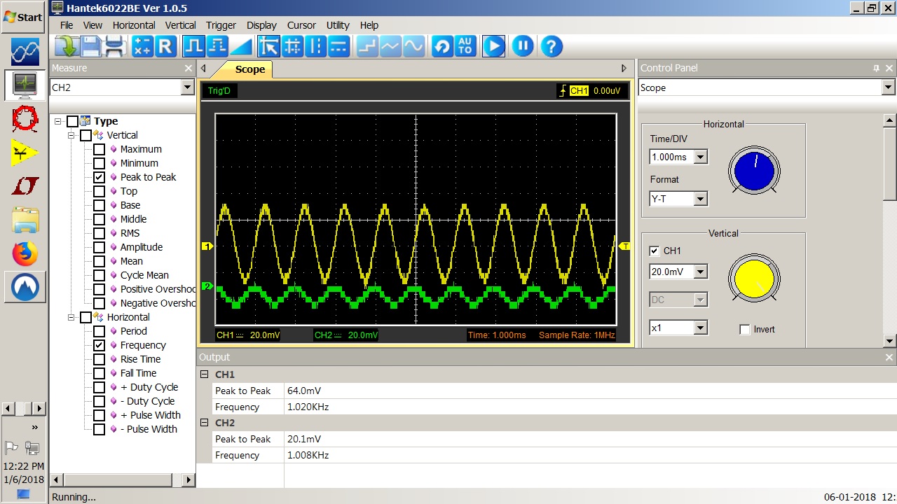
I put a 1Khz signal on it and at 25 - 30 mv it is clipping the signal. I turned it up a little so you can see it clearly. So my take on it is the center stage is so starved for voltage it over drives with a small signal. This clipping = detection in an RF circuit. So connect an antenna and over drive to receive a signal. Now what to do?
I changed Q3 emitter resistor to 510 ohm and inserted a 200 ohm in Q2 emitter circuit. The reading were taken after the changes. Notice point 7 went up 1/2 volt. This may allow a little more wiggle room before the signal clips. Let's see what the scope shows.
The green is the input and the yellow is the output. Looks good but I'm just at the point clipping started before.
Back to the antenna test.
This is what I now have with the antenna on the input.
I added a 4 mh choke on the input and I have a little 60Hz but the RF is basically gone.


Hi I did something like that when i was kid in 1979 and was the best low noise amplifier ever made at that time with few components. I did not have the 10Kohms resistor at the input to the ground. That is keeping the first transistor blocked and the second transistor saturated. 0.6V gate voltage = starving gate current then the transistor is off. try it . I did had different Vcc decoupling that was cascaded.
ReplyDeleteit also need an resistor at second transistor at emitter ca 100ohms
ReplyDelete