These sims gave some interesting results. Be fore warned don't let common opinion interfere with the test results. I am changing component values to see how they effect Z matching and if they are needed for good performance. I have been told some components are redundant and unnecessary. I was also told the circuit simply will not work. I just testing the circuit with and without the "redundant" parts and changing values to see the effect on Z matching. I'll let the sims tell the story.
The 1N5817 is not a prime candidate for a detector based on it's Is and N. They are both high.The dual diode is a waste according to the same source. It seems to be doing well in a circuit designed around its parameters. The sim ahead of this one I removed the redundant diode and unneeded choke????
Anyway I found the results interesting and hope you do too.
Saturday, June 2, 2018
Thursday, May 31, 2018
AM detector in SPICE
Here I am using 100 MHz. The sim is slow.
I changed it to 10 MHz and it sped things up a bit. So click the link and adjust the components, even remove some to see the results. I used the values from Morgan's book for boys. Simply short or remove the parts declared to be unnecessary and see the effects.
detector.asc
I used LTspiceIV it will work in later versions. Look at L1, C2 and C3 voltage and current. These reading will explain a lot about what is happening in the circuit.
Tuesday, May 29, 2018
LCR meters
You can wind a couple of extra turns on a solenoid coil and the unwrap some if needed but with the basket weave it would be a little more difficult. Following the design laid out by someone else would just be follow the pattern. If you want to do your own and know the value you made you can get a LCR meter is several types. Some LCR meters are made in a case that look like a multi-meter. Some transistor testers have capacitance and inductance meters built in. Here are a couple to look at if you feel the need for one.
The first one is less than $10. The bottom one is less than $50.
There are others, these are the first three my search found. You can also find LC meters. The LC meter would be more accurate and possible a little more expensive. It depends on how many coils you will be winding. It also help ID the unknown capacitor. Some junk box treasures need ID'ing after being hidden in the treasure chest for a time!
The first one is less than $10. The bottom one is less than $50.
There are others, these are the first three my search found. You can also find LC meters. The LC meter would be more accurate and possible a little more expensive. It depends on how many coils you will be winding. It also help ID the unknown capacitor. Some junk box treasures need ID'ing after being hidden in the treasure chest for a time!
crystal radio step 5
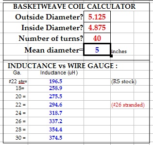
So we could use a 182uh coil. How to make one is the question. Looking back at professor coil we see wire options. If you set the pins at 5" and wind an over - under wrap the medium would be 5" so I use that for example to see how the turn count works out.
Looking at the chart you see it list a range of wire sizes and calculates the table each time you change the turn count. The table is in standard wire size and you want to use litz so how does that work? Time to look at the supplier's catalog.
Litz catalogue
Go to page 129 for the wire specs. Skipping over the math just look at the wire sizes and construction.
For medium wave you need #46 or #48 wire to see the benefit of litz over magnetic wire or stranded wire. Mike used 660/46. His wire was 660 strands of #46 wire. Now look at more of the data.
To use the data from the calculator you need to know the wire gauge or OD so you can look it up on a wire chart.
Mike used 660/46. The yellow high light 3rd and 4th column. So 660/46 is 1st column - #18 wire gauge equivalent.
So tabulating the results from above:
10T - 23.6 uh
20T - 81.8 uh
30T - 162.6 uh
40T - 258.9 uh
He said he used 182 uh @ 36 turns but he inter-wound a smaller wire which would effect the inductance. The calculator assumes the coil is close wound. In order to get an accurate result it needs the width of the basket (length of coil).
The program uses turns per inch and turns to calculate the coil length. With the interweave we have some room for error. The value given is a measured value the calculator says 218.9 uh. Stretching the coil to insert 18 turns of second coil will reduce the value.
That's about all I know. You should be able to use what you have available and make the coils using the program.
Good luck.
Looking at the chart you see it list a range of wire sizes and calculates the table each time you change the turn count. The table is in standard wire size and you want to use litz so how does that work? Time to look at the supplier's catalog.
Litz catalogue
Go to page 129 for the wire specs. Skipping over the math just look at the wire sizes and construction.
For medium wave you need #46 or #48 wire to see the benefit of litz over magnetic wire or stranded wire. Mike used 660/46. His wire was 660 strands of #46 wire. Now look at more of the data.
To use the data from the calculator you need to know the wire gauge or OD so you can look it up on a wire chart.
Mike used 660/46. The yellow high light 3rd and 4th column. So 660/46 is 1st column - #18 wire gauge equivalent.
So tabulating the results from above:
10T - 23.6 uh
20T - 81.8 uh
30T - 162.6 uh
40T - 258.9 uh
He said he used 182 uh @ 36 turns but he inter-wound a smaller wire which would effect the inductance. The calculator assumes the coil is close wound. In order to get an accurate result it needs the width of the basket (length of coil).
The program uses turns per inch and turns to calculate the coil length. With the interweave we have some room for error. The value given is a measured value the calculator says 218.9 uh. Stretching the coil to insert 18 turns of second coil will reduce the value.
That's about all I know. You should be able to use what you have available and make the coils using the program.
Good luck.
Monday, May 28, 2018
Crystal set step 4
Alan Yates has a some good data I will just provide the links.
Basket weave jig
Using a compass to layout the cords
Thank you Alan.
Basket weave jig
Using a compass to layout the cords
Thank you Alan.
crystal set step 3
Now let's tie it together. Reactance is expressed as X. The subscript c or l says capacitive or inductive reactance.
With a fixed coil the capacitor is being adjusted to see the effect. At low frequency the Xl is low and the coil passes the current. At some point Xc=Xl and they cancel. The circuit resistance (impedance = Z) is very high. As the frequency increases Xl becomes high and Xc decreases. The coil blocks current and the capacitor passes current. Ao at our radio station frequency we want Xl = Xc. Now back to the calculator.
The example circuit we are using as our pattern used a 182 uh coil so I went with that. Assuming some stray capacitance I use 50 pf as our low setting on the Vcap. The calculator says our resonant frequency is 1670 KHz. Look to the left and it says both Xc & Xl = 1907 ohms. The point is Xc = Xl so it is at resonance.
With the sane 182 uh coil I change the Vcap to 480 pf. We see Xc & Xl = 615 at 540 KHz. So the 182 uh coil in combination with the Vcap chosen wil cover 540 Khz - 1670 Khz as long as we have no more strays than I allowed in the example. If the strays are less we will have a little more range in the adjustment. The next step is to see how to wind the coil.
With a fixed coil the capacitor is being adjusted to see the effect. At low frequency the Xl is low and the coil passes the current. At some point Xc=Xl and they cancel. The circuit resistance (impedance = Z) is very high. As the frequency increases Xl becomes high and Xc decreases. The coil blocks current and the capacitor passes current. Ao at our radio station frequency we want Xl = Xc. Now back to the calculator.
The example circuit we are using as our pattern used a 182 uh coil so I went with that. Assuming some stray capacitance I use 50 pf as our low setting on the Vcap. The calculator says our resonant frequency is 1670 KHz. Look to the left and it says both Xc & Xl = 1907 ohms. The point is Xc = Xl so it is at resonance.
With the sane 182 uh coil I change the Vcap to 480 pf. We see Xc & Xl = 615 at 540 KHz. So the 182 uh coil in combination with the Vcap chosen wil cover 540 Khz - 1670 Khz as long as we have no more strays than I allowed in the example. If the strays are less we will have a little more range in the adjustment. The next step is to see how to wind the coil.
Subscribe to:
Posts (Atom)