Friday, July 26, 2019

A closer look at the trumbone tuner

Let's look at it without the coil first. First question is at what frequency is 130 mm one quarter wavelength?
We can transpose the wavelength and frequency and we find the frequency is 300,000,000 / (.13 X 4 ) or roughly 577 Mhz.

 
If we look at  Zin with a 1/4 wavelength  transmission we line see the DUAL of Zl. (2-12-19 I posted a link to Mr Turners book on transistor theory) Mr Turner explains the theory of duals in his book. The simple statement is we see the opposite at the input and output. Some text say we see the conjagate.
In other words with the load end open we see a short. With the slider on the load end we see an open feed end. With a line shorter than 1/4 wavelength we see capacitance.
So any length will resonant at some frequency and represent a reactance at other frequencies, Below 1/4 wave length we see capacitance. Adding inductance will cancel the capacitance and make the line longer electrically.

The article from wiki says adding the inductor lengthen the antenna and lowered the resonant frequency. So Amie made the loop long enough to resonant at a lower frequency by adding tuning components (mainly the loading coil and then added the shorting strap to make it adjustable.


Here are some more variations. Notice the top right antenna has and inducter sticking off the side.
While Amie found an application in the broadcast band her system would be more common in microwave. When the wavelength is measured in centimeters lead lengths becomes more critical.
The recap:
A parallel resonant circuit is high impedance. A shorted 1/4 wavelength transmission line produces a high impedance on its input. This equals a parallel resonant circuit at that wave length. At other wavelengths the impedance is lower. Using the slide makes it adjustable.

Wednesday, July 24, 2019

Air band build - unique tuning

 Amie's TRB post

************************************************
EDIT
Sadly the link is broken
To much theory for TRB maybe?
I did copy the trombone tuner to the next post before it was removed.
************************************************

A tip of the hat for you kid. That is clever indeed. It shows a firm grasp of the components, and an understanding of how they work together.

My friend made one based on this design.

A PDF of the radio he made.

We were discussing this coil

In his build he used a string around the coil adjusting screw.

Maybe this would be a good method?

The indicator mounts where the arrow 3 is. Instead of the drum mounted on the variable capacitor he wrapped the string around the slug screw on the coil. Could Amie's trombone be mounted with the slider attached at arrow 3? This would allow tuning from the front panel? The round drum could hold the indicator or the drum could be replaced with a spring (from a pen) and the indicator mounted on the vertical string. (arrow 4)

Food for thought.


Sunday, July 21, 2019

Using feed thru capacitors for isolation


feed thru capacitors


They are still being made but are mostly surface mount today. I saw some for several dollars each. The best price I've seen is around 3 for a dollar in larger quantities. The ones above have no pin installed. I was thinking about making something like them. Still considering the construction details. I'm storing this info until I get some shop time for the actual project. You might ask what are the good for?

The three terminal capacitor IS a feed thru capacitor. My low frequency application will be using them for isolation between stages. For example when feeding a DBM with a RF signal and a LO signal the stages must be isolated. The leads act as antennas radiating and receiving signals. To prevent the cross talk the stages will be separated by metal shields. The signal and supply leads will feed thru the shield using feed thru capacitors. I have a few on hand but intend to make some for this project. Next step will be to get the shielding and breadboard.

HINT: In microwave the vias have capacitance and act as feed thru capacitors.

QUESTION: could a via work in my circuit?

I will be exploring this next.

Friday, July 12, 2019

Simple AF amp with a kick

transformer
This amp will drive an earbud with the touch of a finger on the input. R5 and R6 are a 10k pot.
Top plot is input lower plot is the transformer secondary. Shielding the input and battery leads is necessary to prevent motor boating.

Simple FM detector

As simple as it can be stated: when the input is at the tank's resonant frequency the system is in balance as shown in (B). As it goes above or below resonance the circuit goes out of balance and produces an output. AM will pass through the detector.  Q1clips the peaks to prevent AM bleed through.


Tuesday, June 18, 2019

Transistor TRANfer reSISTOR -current controlled resistor - voltage controlled current source ?

I will try again to show the transistor action. Whether you want to see it as a voltage controlled current source or a voltage controlled resistor the test should help with that.
Keep in mind semiconductors are non linear and Ohms Law is still in effect. E=I*R and we can not change one parameter without effecting the others. First how can we transfer resistance in the device? Apply a forward bias voltage to the base - emitter junction and the base - collector junction resistance will change. The main parameter is ß (beta). Beta is the ratio of current in the base and the collector. This too is non linear so we must read Beta at our operating point for it to be accurate. First let's look at the beta of a transistor at three points.

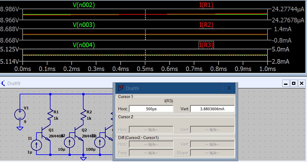
The three stages have 1uA , 10uA and 100uA base current.
Q1 has 21uA so beta is 21/1 = 21.
Q2 has 320uA so beta is 320/10 =32.
Q3 has 3.9mA so beta is 3900/100 = 39.
Notice a 100 fold change in base current almost doubles beta.
Let's see what happens when we produce a 10 fold increase in collector load resistor.


Looks much the same. Let's increase the collector resistors again.

I added the collector voltage so you can see the circuit will current limit when the load resistor drops the supply voltage.
Raising Vcc to 9 volts raises the collector voltage. The current through the load resistor is the same as before so the drop across it is the same. The 'excess' Vcc is on the collector.
The next 3 screen shots show even with Rc increasing from 50 Ohms to 1K and Vcc going from 5 volts to 9 volts the collector current is the same.
This should make it clear a change in base current will produce a change in collector current. If the supply voltage and collector load are within the circuit limits that current will be reasonable close to the same for a given base current and device beta.
The next step would be to explore how to set the base current. Actually I did that here: Fixed Base Biasing 

The fixed base biasing is ok for small signal hobby circuit but is prone to thermal runaway. The next step would to look at methods to stabilize  the circuit.