Friday, July 6, 2018

colpitts oscillator

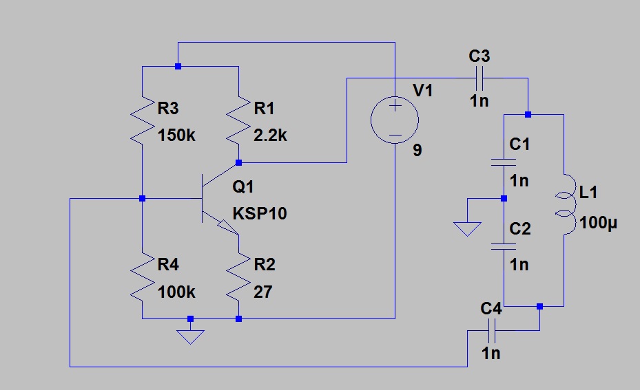
The teacher says build the DC bias network first. This is it. In order to have an oscillator I need a resonant circuit.
L1, C1 and C2 are the tank. Capacitors in series add as resistors in parallel so I have a 500pfd cap a 100uh coil forming my tank. This will give a resonant circuit at about 712Khz.
I take a signal from the collector and feed the tank. Then send feedback to the base. That is C3 and C4s jobs.
Now I power the circuit and it sings. It is producing a 8 volt pk-pk signal. Lowering the value of C3 and C4 will produce a lower output. Lowering C3 will reduce the feed to the tank. Lowering C4 will produce less feedback to the amplifier input. In order to have oscillation we need a gain higher than 1. It simply has to overcome the circuit losses. If we had a load on the tank we would need more feedback to replace the signal drawn by the load.

The capacitor divider divides the AC voltage the same as resistors will DC.


You should have no trouble seeing the resistors as a voltage divider (for a DC circuit)


The capacitors provide the same function in an AC circuit. The reactance is set by the frequency. The series circuit has the same frequency so we can use the ratio of capacitance and do the division. Xc = 1 / (2 * pi * f * c) so the larger c has the smaller drop.
Vc1 will be greater than Vc2. With resistors  we use a formula such as Vr1 = Ea * (R1 / (R1 + R2)).
With parallel resistors we use:
Rt = 1 / (1/r1 + 1/r2 .......) When we do this we are applying Ohm's law and assuming a voltage of 1 volt.
I=E/R Ir1=1volt/r1 Ir2=1volt/r2 It=Ir1+Ir2 R=E/I
Rt=1volt/It. See it is Ohm's law assuming 1 volt applied.
 You can solve the capacitor circuit using the same approach BUT remember capacitor in series add as resistor in parallel so use the conductance to solve it.


Tuesday, July 3, 2018

measuring the input Z

You could place a pot in series and adjust Vin to 1/2 Vg then the pot would be equal to Zin. If you use this approach and do not measure both points as you adjust the pot you will have an error 600 Ohms. Remember maximum power transfer is at the half power point. If Zin = Zout the drop across Zin is 1/2 the supply. In this case Zin=Rg + Rs. So the point where we match the impedance is not determined by the pot alone.
I have the generator set to 10mv and have a measured Vg = 9mv I'm losing 1mv across the gen resistance.
Here I reduced the resistor and read Vg and Vin.
I increased the resistor and measured Vg and Rin.
The point where Rs = Zin would give the best results. Setting Rs to drop 1/2 Vg gets us close to that point but Vg varies with load so it is a juggling act. Using two meters and adjusting for the same reading could be an acceptable alternate.

Friday, June 29, 2018

2N7002 2 Stage AF amp

This was so simple even I could do it. No math just pick some values to limit the current and set the bias. I'm looking at about 1 ma current draw.

 I mv in 500 mv out. 1 mv will rattle my earbud 1 volt is loud enough with my ceramic head phone.


The frequency response is well beyond my hearing range. I put it on a bread board and put a diode, coil and antenna on the input. It plays my local station.
I made this circuit using 2SK669's  before and it was a good build also.

Thursday, June 28, 2018

lacing a parallel cable run

Usually when we lace a bundle we just wrap the string around the wires but what if we want the wires to lay flat?
I bent a hook in the end of a piece of wire to make it easier to feed the ribbon through
Lay the ribbon on the cables with a long enough tag to tie it off when finished.
Take the ribbon under and over to the first gap between wires.
Wrap under the main tag and back up then down through the second gap.
Wrap the tag and back up.
Keep spiraling down - over - up and down the next gap until you reach the far side.
Now bring the first tag under and up the right side. Tie the ends off and trim the ribbon.
Repeat at the other points needing tying.
If you use dental floss you can get a needle with a big eye and sew the wires in place. Using a needle will aid in separating the wire too. If they get a twist you can put the needle between them and iron the twist out by running it down the wire run.

Sunday, June 24, 2018

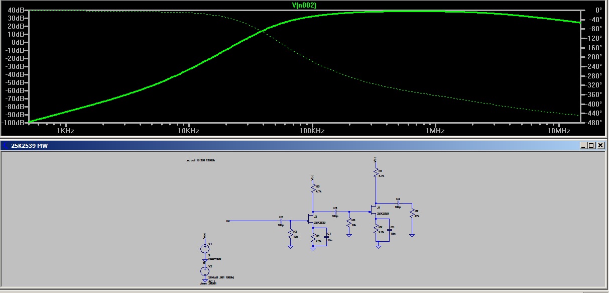
A MW RF amp using the data from the previous post

500KHz to 1500KHz
Expanded range to show more roll-off
The yellow is the half power points. The red is the MW band.
 Increased range to show roll-off.
Different transistor. You can try others to see which are useful in the desired application.

Saturday, June 23, 2018

amp input characteristic vs bandwidth


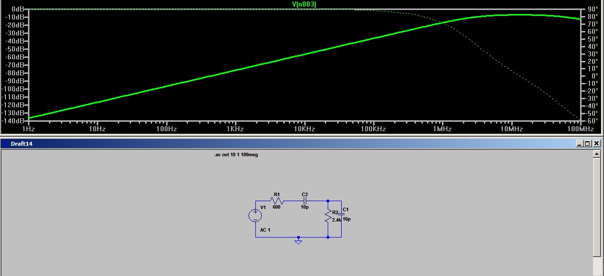
Setting the parameters for a stage with a 600 Ohm generator, 10ufd coupling cap, 2.4k Ohm input Z, and 1 nfd input capacitance.  10 Hz to 300 KHz bandpass. Now change some values and see what happens.
Reducing the input capacitance to 10p raises the high end to 30 MHz. What determines this value? The transistor inter-electrode capacitance, Beta, and strays. How would we reduce it?
Raising the input Z made the response worse.
Reducing the coupling cap value and the input cap gives a better high end response.

So the question becomes how can the designer control the circuit reactance? Maybe the question is how to work with what he has to get max benefit?

So build the circuit in SPICE and try different values. Look at the transistor datasheet and see what your real world values will be. Above all else have fun.


high-low corner and frequency response

The half power point is .707 signal out or when Xc = Rl in a RC coupled circuit. I will show some RC circuits and some transistor amps to examine.
50 Ohm response rolls off below 90MHz
Looking at the low corner.
Here I have 10 mv in and 5 mv out

My 2N3904 roll off is less than 50 MHz

Changing the caps shifted it slightly above 50 Mhz
usiong 50 Ohm I/O

600 in 50 out

50 in 600 out

600 in 50 out and smaller cap

50 in 50 out and small cap. observe the scaling.


You can see the RC circuit response is predictable but adding a transistor will cause the curve to shift. The transistor parameters come into play and must be accounted for. Some things are beyond the designers control. So we need to use the manufactures data sheet to see if out transistor will serve our purpose.

It's a simple circuit you can type into SPICE is a minute or two but playing with it can reveal a lot about how the coupling system responds.