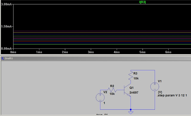
I applied 1 volt to the base through a 10K resistor. This sets the base current used in the test. I am stepping the collector from 3 to 12 volts in 1 volt steps. As you can see the collector current is very close to steady state.( we'll look at the reason for the small change later.)
The voltage Vce is at saturation. In other word the 10K resistor is limiting the collector current and the base is filling up with carriers that cannot be drawn away. To put it another way. The voltage drop across the 10K resistor would have to exceed the supply voltage for more current to flow. The transistor resistance and the 10K resistor form a voltage divider. The semiconductor resistance varies with the current flowing in the circuit.
With a 1K resistor for the load the transistor can supply the current and the voltage drop across it is close to the applied. Again the emitter inject a set number of carriers with the applied bias and the collector draws them away. The drop across the 1K resistor remains the same so the collector voltage increases as the supply increases.
With a 1 ohm resistor we see basically the same step with supply change. As I said before the collector potential draws away carriers until the out flow equals the emitter injection and then the circuit is at equilibrium. Vce is equal Vcc - Vr3.
This is what happens when we change the current through the base. Stepping E from 1 to 10 in 1 volt steps. Look closely and you can see the family of lines. E steps to a point and V1 steps through its values and E steps to the next point. Ic varies slightly as V1 swing threw its range.
Cutting the Vcc in half doesn't have that much effect on Ic.
Cutting Vcc back to 12 volts still give 2.45ma. Notice the base emitter voltage is swing slightly. The transistor has a resistance which varies with applied potential. With higher voltage drawing the carriers away at a faster rate the opposition to more being injected is less and as higher currents flow the voltage drop increases. So the final change is determined by the material resistance and the injection opposition. Doping heavy increases the ability to inject and reduces the resistance but there is more to it than that.
The problem with computer volt meters can be resolution. While we benefit from the wiggly lines we can also see more than a simple volt meter will display. Here I set the range to show the base voltage swing with a Vcc from 10 to 100 volts.
The change is still there but as I said before it is steady for practical purposes. Rbe in series with the 10K resistor form a voltage divider that drops the Vbe. Generally the 10K is large enough that changes in Rbe can be ignored. That effect is showing up in my sims. I guess that would be the topic another day.
in summary.
TRANSfer of reSISTance or transistor as we say.
Low resistance emitter to high resistance collector circuit.
inject carrier into the emitter and let the collector resistance fall. We could use Fermi level, barriers etc. but the sims tell the story quite well???


