Thursday, December 7, 2017

Another method for mounting the surface mount FETs


The tool required is chisel edged NOT knife edged. You could take a hacksaw blade and break it in half. Grind the teeth off and bevel the end at anything between 30 and 45 degrees. This would produce the ideal tool. If you prefer to buy the tool an exacto knife will work but you will use the back of the blade NOT the knife edge. Now onto the project. We need to mount 2 BF2040s on a PC board.the first step is to clamp a ruler on the board as a cutting guide.
I am using a small vise grip you can us any clamp you have.
This is a plastic cutter. It would probably work but I am not using one.
This box cutter might be a good tool for the job also.
I am using an exacto knife. Just run the back of the blade against the ruler.
As you can see it makes a groove the width of the blade.
I clamped the ruler against the other side and made the cut. I have divided the board into 4 sections. A quick check with the ohmmeter proofs the sections are isolated.(if not pay attention to the ends of the cut.)
Another cut off the other side and I have 6 sections.
I drilled a pilot hole on the two crosses.
I used a circle cutter, backwards. Scraping not cutting.
One more circle and the board is ready to use. When the FET is soldered on the board the four sections in the circle will be my tie points. The other six section can be used for I/O and power connections.

Maybe I can mount the BF2040s tomorrow.


Wednesday, December 6, 2017

mounting BF2040Ws a picture story book.


The subject of mounting surface mount compoments comes up every so often. I mounted a couple for a pre-amp. documented the process so I will not forget how I did it.


This is double sided board that can be cut with a pair of scissors. You could just cut some squares and position them very close together. I wanted to try spacing them out a bit.


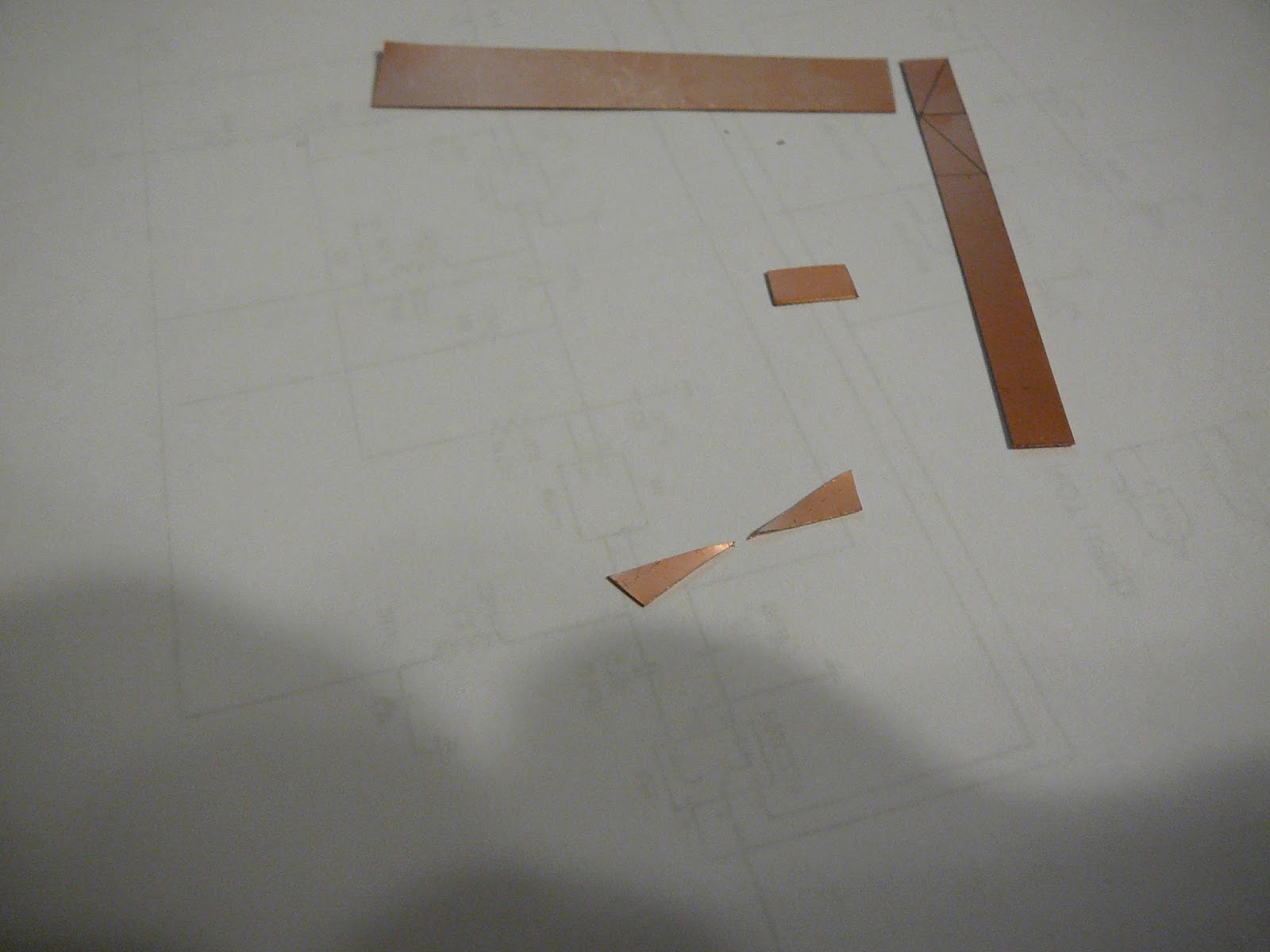
I cut a couple of rectangles and then cut them on a diagonal. The long points should be easy to position without crowding the pieces.


A little glue and this is what I got.


I soldered the parts on the board.


I drilled a hole in each triangle.


with pins in place i'm ready to mount the resistors.


I soldered the pins to the board. They help keep everything in place and it could make a bad joint to the board with wires in place?


I will not bore you with a component by component installation.I put 5 volts amp. My scope on the output was showing noise. When I put my hand close to the input the noise would jump up. I put an earphone on the output and heard nothing.This is good. If it was oscillating it would make some squeal or howl. I put a diode across the earphone and hear the sound of a receiver between stations. Several signals at once.


This amp is as simple as it gets. I used 2 100K resistors to set 1/2 Vdd on G2 through a 10K resistor. I applied Vdd to G1 through a 10K resistor. A 50uh inductor applies Vdd to the drain. Ground the source. DC biasing is done. I put a 1nfarad cap on the input, output, and interstage coupling. I put a 1nfarad cap from G2 to ground. and it is done.


You could us the idea of the triangles and glue them on a copper clad board to do a Manhatten style board.
The spacing of the parts match the hole pattern of a prototype board so you could solder them on a proto board or use the proto board to mark the layout.

This was just intended as food for thought. This might be a better method but requires more material. The two could be used and do a Manhatten build with three layers.

The three layer board

Saturday, December 2, 2017

Solar Farm HookUp

The red box contains the Solar Farm.
The blue box would be the distribution system.
The farm produces 11Kv which goes up the pole and connects to the grid. The power company would step it back down to supply the residence.
Is this correct?

Sunday, November 26, 2017

Adjusting the supply on an amp to see the effect.

A request was made for a 1.2 volt amp. The idea was to make a radio powered by a single rechargeable cell. My last three post were in response to that question. Tonight I will present a the amp with different supplies to see how it would work at higher voltage levels.
The input will remain at 10 uv.
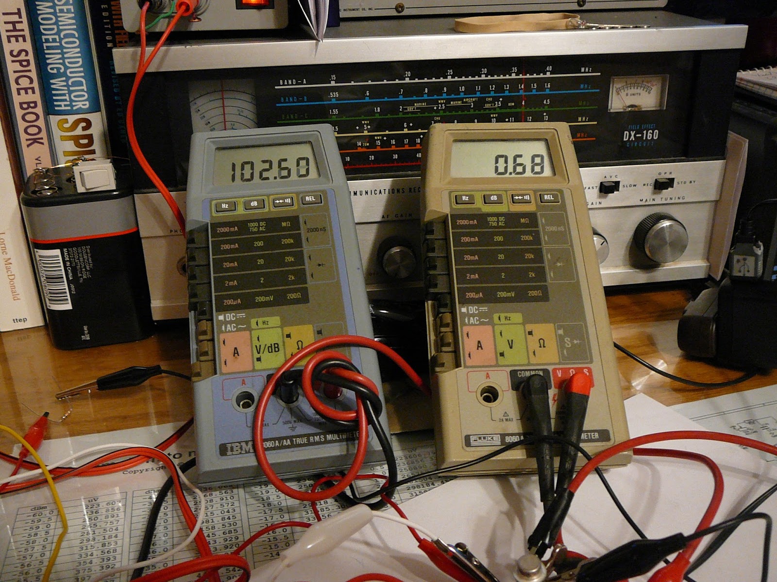
Here I adjusted the components and have 850uv output at 1.2 volt in.
I raised the power supply to 1.5 volts and get 1.45 mv out.
Here I make the big jump to 6 volts and get 12 mv out.
At 9 volts we get 20 mv out.
At 12 volts we get about 28 mv.
With the same circuit there is quite a change in output when the supply is varied.
The goal of a 1.2 volt supply radio is possible but it would be a lot easier to use 1.5 volt or more.

Wednesday, November 22, 2017

modified amp for more gain

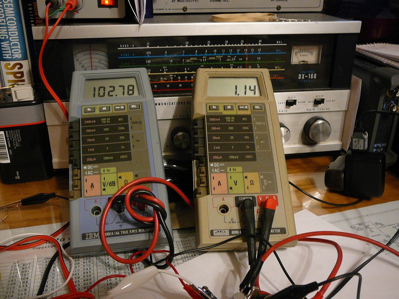
I made a couple of change to the resistors and added gain.
10 microvolt in and 1350 microvolt out.
This cost me 3 ma battery draw.


Tuesday, November 21, 2017

Did a sim on the amp I posted last night.

I located My model for the P416B transistor and did a simulation. I did the sim at 2 MHz and 10 micro volt input.
Here I am probing C2.

Here I am probing C4. 10 micro volts input gives about 850 micro volts output.
My test gave better results than the sim? My model may be a little off. Close enough for me though. Anyhoo, it is one possibility for a 1.2 volt amp. The builder could possibly improve it by tweaking some component values.

I made the board last night with sockets so I can test the response of different transistors. It was not designed to be optimized for a specific transistor. I have some old tarnished ones I can not read the numbers on and thought I would use a couple in my AF amp for the AER. Chances are I'll stick with the K669 or BF2040. So many choices, so many circuits to build and test!
The fun is in the build so just build something.


1.2 volt RF amp


The power supply is set at 1.2 volts. The two meters are on the input and output. I switched the meters to assure they were not giving false indication due to calibration errors. I did some readings on the millivolt scale and  some on db.
The generator is set at 1 MHz.